文章转自ADI官网,版权归属原作者一切
Q: How accurately can the junction temperature of a high-speed amplifier be estimated from the data sheet specifications? Can the junction temperature be easily measured?
A: Many years ago, a fellow applications engineer and I talked about the classic method of calculating junction temperature from the ambient temperature (TA), power dissipation (PD), and thermal resistance θJA), as shown in equation 1.
TJ = TA + PDθJA (1)
He told me of an alternative method that obtained the junction temperature of a popular 3-terminal regulator by using an on-chip output stage protection diode as a temperature sensor. His company used the protection diode to measure the junction temperature of the regulator during routine testing and evaluation. This temperature sensing technique can also be used on a high-speed op amp.
In Figure 1, diodes D3 and D4 protect the op amp from damage caused by electrostatic discharge (ESD). Diodes D1 and D2 protect the input differential pair of a high-speed op from the damaging effects of reverse voltage breakdown. Dedicated diodes and PN junctions are commonly used as temperature sensors, but ESD and input protection diodes can also be used to measure temperature.
The principle of using a diode as a temperature sensor is straightforward. With a constant current applied, the voltage across a diode or PN junction will decrease by approximately 1 to 2 mV/°C over temperature. The voltage change over temperature can be used with a look up table or an equation to calculate a temperature for any given diode voltage; in this case, the die temperature of a high-speed op amp can be determined.
The diode voltage vs. temperature can be characterized by placing the amplifier in a temperature chamber with a constant current applied to the ESD diode junction (0.5 mA was chosen to avoid the effects of self heating on the diode junction), as shown in Figure 2. Set the temperature to 25°C, “soak” the part for a few minutes, and record the voltage across the diode. Repeat at –40°C and +85°C. With three points taken, the slope can be determined.
An expression for the diode voltage over temperature is derived by using the point-slope form of equation 2. The temperature for any diode voltage can then be easily calculated.
y – y1 = m(x – x1) (2)
Using the above procedure to evaluate the ESD diodes on the AD8063 general-purpose 300-MHz rail-to-rail amplifier yielded a slope of –1.2 mV/°C. Substituting into equation 2, results in:
y = –0.0012x V/°C + 0.887 V (3)
Solving for x enables the die temperature to be calculated from the voltage reading:
x = –833.3y °C/V + 739.2°C (4)
Next, the AD8063 was set to dissipate 1/4 watt; this dissipation provides enough voltage swing to accurately measure the change in diode voltage. Operating on +5-V and –3-V supplies, the AD8063 was configured to drive a 20-ohm load, as shown in Figure 3. The amplifier’s quiescent current is 5.5 mA, so it dissipates 44 mW with no load. A 1-V dc signal was applied to the input, producing a 50-mA load current at the output. The drop across the output transistor is 4 V. With a 50 mA load, the amplifier dissipates another 200 mW, for a total of 244 mW. The AD8063 was allowed to heat up for a couple of minutes. The circuit was switched back to the configuration shown in Figure 2, and the diode voltage was read. The average voltage was 817 mV, corresponding to a junction temperature of 58.4°C.
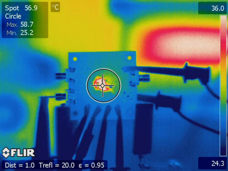
To verify the results, an infrared camera was used to measure the case temperature. According to our packaging engineers, the junction temperature is approximately 1°C to 2°C higher than the case temperature. The IR measurement yielded a case temperature of 58.7°C (see Figure 4). Accounting for the thermal effects of the plastic package yields a junction temperature of approximately 60°C. The diode voltage and IR measurements thus provided good correlation.
Calculating the junction temperature using equation 1 and θJA of 230°C/W (from the AD8063 datasheet) resulted in a junction temperature of 83.7°C, a difference of 43%! Working equation 1 backwards provides an actual θJA of approximately 130°C/W. The θJA found in this datasheet is very conservative, ensuring a robust and reliable design. For more realistic junction temperatures, the ESD diode measurement technique proved to be a reasonable method for obtaining accurate die temperature.
A future article in this series will show how an ADM1021A system temperature monitor uses the input protection diodes to directly measure the amplifier’s junction temperature.
The author would like to thank Glen Wiegand and Jerry McCarthy for their help in collecting test data.