文章转自ADI官网,版权归属原作者一切
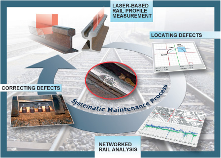
A new, systematic maintenance approach now makes it possible to measure, locate, and fix rail- and tramway defects when they appear. Mature railway-engineering know-how and cutting edge technologies—including Blackfin® processors and graphical system design techniques—combine to improve and optimize public transportation.
Over the last decade, public transport by rail or tram has become a popular means of transportation. The number of passengers seeking a comfortable and safe ride is constantly rising. The increased loads call for higher train speeds and shorter stop intervals, thus exposing rails and tramways to increased mechanical stress. This, in turn, causes unavoidable early wear and annoying or dangerous defects (Figure 1).1 Dealing with the results of these stresses on rails and tramways requires increased emphasis on monitoring and maintenance. Analog Devices Blackfin2 processors and National Instruments graphically programmable LabVIEW™3 technology can play a central role in rail inspection systems, acquiring accurate measurements of field data, and storing it for further action. This can result in longer operation lifetimes for rails, improving economy and reliability in the public transport service.
Rail Tracks—a View “Under the Hood”
When new rail- and tramways are laid out properly, quality assurance verifies correct track positions prior to concreting. Inevitably, as time passes after installation, defects may start to creep in during daily operation. These defects are caused by the stresses of mechanical contact between the wheels and the rails as part of a highly complex spring-mass model, with dynamics ranging from the train’s chassis and loading to the railway foundations. In Europe, the critical parameters and tolerance windows of the defects are classified according to railway engineering standards.4–16 The goal of rail maintenance programs is to discover and measure the irregularities—and keep them at acceptable levels.
Rail Track Geometry
The track gauge, or distance between two rails, affects the side-to-side motion of the train. This motion keeps the spot where the wheel and rail meet constantly moving to minimize wear-out.
Variation in the track inclination can make passing trains shake and shudder. Typically caused by yielding of the railway foundations, inclination defects can also be caused by surface irregularities such as corrugations and holes. Some systematic inclination profiles, such as banking, are necessary, however, to minimize passenger discomfort caused by acceleration forces when a train is riding into and out of a curve.
The correct track-to-track spacing prevents any chance of collision when trains are passing one another at high speed.
Longitudinal Surface Profiles
Cracks and breakouts are among the most feared defects, since they can lead to catastrophes such as derailing. Corrugations—wavy irregularities with a characteristic wavelength from 20 mm to 100 mm—are annoyingly noisy when their amplitudes exceed 0.05 mm. With 0.3-mm peaks, on the other hand, the vibration can cause irreversible damage to the railway bed. Corrugations move along the rails, and science is still not clear on where they originate. Single holes are mostly generated by turning or jumping wheels and can be described mathematically with polynomials. They’re responsible for the sudden bumps on a tramway ride. Regular bumps that are often experienced on older railways are due to the welding interfaces of the 18-meter railway sections.
Cross Sections
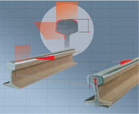
The head geometry of a newly installed rail follows an exactly calculated contact geometry, which optimizes the critical wheel-to-rail interface. The shape is described by tangential lines and specific radii, providing horizontal guidance to allow the wheel to roll off economically, smoothly, and safely (Figure 2).
Measure the Rails
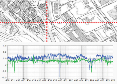
The key requirement for systematic and target-oriented rail maintenance is comprehensive knowledge about the current state of the rail- or tramway network’s geometry. This is achieved by a smart measuring strategy that combines odometer results (distance measuring), track geometry, longitudinal profiles, and cross sections with exact GPS locations. All these parameters are acquired by mobile metering devices or well-instrumented measuring vehicles. The measurement data is initiated and preprocessed by Analog Devices Blackfin processors, then finally transferred into high-level analysis software that allows post-analyzing and pinpointing of the measurements and defects on a digital map (Figure 3).
Track Geometry
The rail gauge is measured using no-contact inductive sensing with accuracies in the 0.01-mm range. Software-based FIR (finite-impulse-response) low-pass filters suppress high-frequency noise, while subsequent moving-average filters ensure that no “pseudo-peaks” occur in a result that is expected to be continuous.
A similar approach is applied to the inclination sensor, which operates like an electronic liquid-level—with an angular range of ±10° and an accuracy to within <0.025°. The physical principle used limits the frequency range to less than 1 Hz.
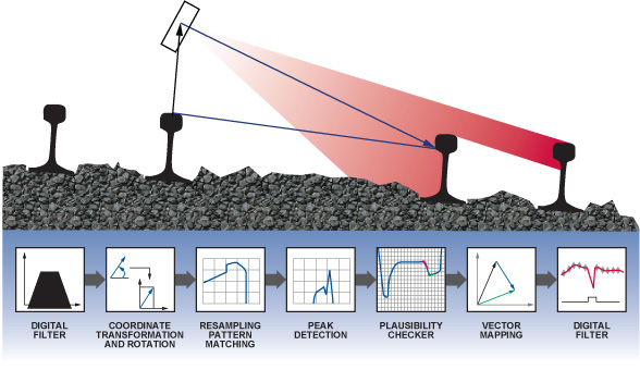
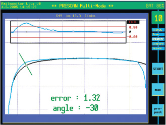
Measuring the track-to-track distance requires a set of complex and computationally demanding floating-point algorithms to compute the absolute horizontal and vertical distance (Figure 4). A high-precision laser beam, attached to the side of a vehicle, wobbles ±5° within a distance range of 1 m to 5 m, under the control of a Blackfin processor. The profile of the neighboring rail is low-pass and median filtered, and transformed from polar to Cartesian coordinates. Further processing, such as vector-rotation and resampling, is applied before the profile passes through a pattern matching algorithm. The goal is to find the exact vector to a characteristic geometric feature within the railhead. Because many obstacles, such as rocks or grass, can be found on railways, this vector is passed through a plausibility checker and a tracking algorithm—to ensure reliable and valid results. All this is done in a 5-Hz loop under real-time conditions.
Longitudinal Profiles
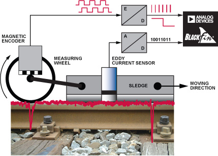
High-speed eddy-current sensors record both rail surfaces with micrometer-grade accuracy (Figure 5). A linear encoder processes signals from a magnetic ring that serves as an odometer and a trigger for the analog-to-digital converters. This signal then goes through a FIR band-pass filter, reducing the spectrum to its characteristic wavelengths. Besides the surface profile, metallurgical irregularities, such as partial hardenings and welding points, are recorded.
Cross Profiles
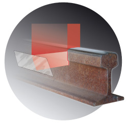
Laser technology is today’s state-of-the-art noncontact measuring principle to get the exact cross section of a rail head. Depending on the required accuracy or capturing speed, either traversing laser beams or laser “curtains” (Figure 6) are used to do the job. Raw profiles are linearized, scaled, and spike filtered in real time.
Older Technology—Metering Devices
Until recently, maintenance staffs used many different metering devices to identify cracks and variances on the rails. Each methodology specialized in recording one specific rail defect, but with few exceptions these mechanical methods lacked precise and reproducible results. In recent years, industrial solutions providers, such as Schmid Engineering, embedded advanced processor technology and state-of-the-art components and methodology into their designs. Such advances in the railway infrastructure business gradually led to mobile and multifunctional rail measuring by smart metering devices.
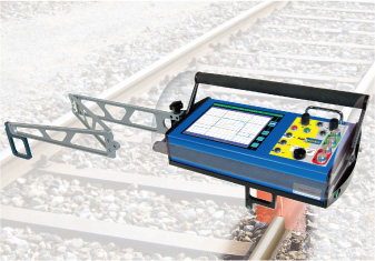
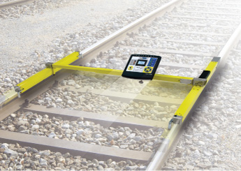
Rail monitor devices (Figure 7) use state-of-the-art technology to simultaneously measure the cross-section profile of the rail, the head height, track gauge, inclination, depth, and ambient temperature—all of which are detected and logged at specifically identifiable locations.
All key characteristics are processed and visualized on site and stored to removable memory. The RailSurf sled (Figure 8) continuously monitors and records longitudinal track parameters, as an operator or a vehicle pulls it along the rails. It carries several sensors, mapping problems such as corrugations, holes, cracks, and variations in rail gauge and inclination. The resulting information can be stored in removable memory or wirelessly transmitted to an operator interface.
Blackfin Processor as the Heart of the System
The Blackfin processor, as the heart of these portable test tools, empowers the convergence of microcontroller and DSP technology by offering dynamic power management for economical battery operation. The MCU circuitry conveniently interfaces with scalable input/output (I/O), such as laser scanners, analog and digital sensors, keyboards, TFT (thin-film-transistor) displays, battery/fuel gauges, and removable media. The DSP portion is dedicated to advanced digital algorithms, such as filters, transforms (FFTs, for example), determination of geometric residuals, or other demanding computational tasks. Recent advancements in graphical system design by LabVIEW embedded modules, with their high-level block diagrams and dataflow-oriented language, offer a direct programming model of the Blackfin processor. This high-level approach with ready-to-use mathematical-analysis blocks and graphical multitasking moves functionality to the next higher level of digital embedded design.
Measuring Machines
A multifunctional vehicle that is driven by a set of five interlinked Blackfin processors is able to record rail parameters for up to 10 km of a railway section with 5-mm point-to-point resolution.
Blackfin Processor #1 allows user interaction over a keyboard and two TFT displays. Processor #2 records track geometry and longitudinal profiles at high speed and embeds GPS information into the measurements, which are then received by Processor #3. Together with cross sections that are captured by Processor #4, all the data is finally streamed to Processor #5, which stores the huge amount of data in large RAM buffers to be eventually saved to binary files on removable media.
Locate the Defects
The acquired measurements are fed into a common software platform that links track geometry, longitudinal profiles, and cross sections with GPS locations and odometer information. Realized with LabVIEW and its toolkits, this platform serves as a common data-exchange and -analysis tool. It interfaces to a variety of measurement devices, vehicles, and maintenances machines. Smart filters applied to the measurements function like an X-ray to locate critical rail defects. The result is a true digital representation of the whole rail geometry. This essential information is then directly usable for actions such as rail repair or exchange. The final data log is wirelessly connected to external databases and CAD software to transfer the results into any customer’s IT environment.
Smart, Powerful LabVIEW Filters Find Defects
Smart LabVIEW filters sift through longitudinal data to find symptoms of interest. Corrugations get detected through a fast-Fourier-transform (FFT) analysis, watching for the characteristic wavelengths in the longitudinal profile. Holes are tracked by comparing the measured profile with memorized patterns and the simulation of the mechanical rail-wheel contact. Cracks show significant transients, so they can be detected by differentiating a moving data window. Finally, unique vibration patterns in the inclination profile are located by continuously running and evaluating analytical models.
The resulting symptoms are also fed into correlating “super-algorithms.” Here the information is either reduced even more, or additional high-level information is extracted from the measured data. An inclination indication, for example, is interpreted as meaningless and is rejected if it is not accompanied by a related signal peak on the rail surface. On the other hand, a cross profile indicating significant wear-out or a longitudinal crack will trigger an alarm.
The main technique used in the evaluation of rail cross sections is comparing a measured profile with a reference. Algorithms based on vector mathematics and stochastic methods align and overlay the two profiles to allow computation of critical characteristics. Vertical and perpendicular residuals directly indicate wear-outs (Figure 9).
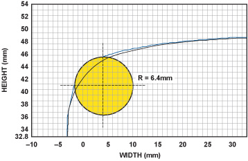
Other parameters include the remaining head height, a correct and well-shaped rail radius (Figure 10), or the gap of an active, closed track switch. Keeping within switch tolerances is a key requirement to avoid the danger of derailing high-speed trains passing the switches. Rail operating companies focus on thorough monitoring of the switches.
Rail engineers can adjust filter-parameter tolerance windows to separate “pseudo-warnings” from true rail defects that significantly influence passenger comfort and transportation safety.
Pinpointing Defects on a Digital Map
GPS information that is embedded in the data allows the located defects to be pinpointed on a digital map. This geographical information adds significant knowledge and new context about locations of railway hot-spots, such as tight curves, switches, and stations. This “Easy-GIS” geographic information system has been made available with the image-processing features of LabVIEW. An existing bitmap of the region of interest, for example, a city, is broken down into single tiles, each given the exact map coordinates. As the rail engineer browses through the set of defects, LabVIEW continuously loads the corresponding tiles from the hard drive into memory and assembles them to form a single JPEG image. This image is then copied into a LabVIEW plot-chart indicator and overlaid with a digital cursor at exact locations of the defects.
Distribute Results to Other Applications
The results are finally transferred to and from higher-level applications. Geometric profiles of critical defects, such as wear-outs and holes, can be exchanged with standard CAD systems for further analysis. This is achieved by the Drawing-eXchange (file) Format (DXF).
Connection to external database management systems is established through ActiveX Data Objects (ADO), which use Universal Data links (UDL) for the connection type and path. A set of high-level virtual instruments (VIs) allows the data platform to perform the most common database tasks such as addressing tables and exchanging data.
The VAG Nuremberg Transport Corporation maintains a matrix of predefined and critical locations in a Microsoft Access database, which is continuously screened for variations. As soon as some hot-spots exceed a tolerance window, an electronic maintenance plan is created and deployed to the measuring devices in the maintenance machines.
The maintenance concept at Zurich Public Transport (Verkehrsbetriebe Zürich, VBZ) relies on a commercial GIS tool with a built-in MS Access database. All infrastructure elements—including rail sections, stations, switches, etc.—are listed and can be visualized on a geographical map that represents the whole tram network of the city—at the push of a button. As with Nuremberg, the state of the rails is continuously monitored as a vital part of a short- and long-term maintenance concept. The LabVIEW platform connects to this GIS tool by the means of ActiveX and .NET mechanisms.
Solving the Problem
The resulting maintenance plan fed back from the IT environment is downloaded into the maintenance machines as quality set points. A pair of Blackfin processors supports the team in fixing worn-out or defective rail sections rapidly and systematically, using several iterative grinding runs to bring the rail back into its original shape.
One of the processors provides the operating personnel with a multifunctional keyboard, a visual of the rails on two TFT monitors, and removable memory. Two laser scanners continuously capture snapshots of cross profiles at 20 Hz and transfer the data online to the CPU over a CAN (controller area network). The processor then calculates the deviation from a reference profile and forwards new set points to the underlying grind unit, which is controlled by the other Blackfin processor.
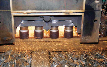
This grind unit consists of a total of six independent grinding pots. Each offers three degrees of freedom with actuators based on a hydrostatic principle. At first the pot moves horizontally either to the inside, outside, or middle of the rail head. Then it rotates to the worst-case deviation and finally moves down until it touches the railhead to start removing the material. The Blackfin processor controls each of these 18 movements simultaneously by applying pulse-width modulated (PWM) signals to the valves that control the hydrostatic actuators. Additionally, six rotation sensors, six translation gauges, 18 no-contact position switches, and six pressure sensors are continuously monitored during this positioning process. While this process took minutes using a traditional approach, the grinding pots are now placed automatically within seconds.
Finally, the grinding pot starts to remove the excess material (Figure 11). Secure and sturdy housings protect the electronics and the sensors from flying sparks, aggressive dust, humidity, and heat.
After the grinding process, the quality is assured by loading a set of profile measurements back into the IT environment using removable media.
Conclusion
A systematic maintenance concept for rail- and tramways has been taken to the next phase using digital embedded design. By taking advantage of low-level measurement and control on the rails, and high-level data-mining and analysis at a central location, an optimal and cost-effective integrated solution for track maintenance has been designed.
Taking advantage of the scalable performance and capability of a Blackfin processor, the metering devices and vehicles used for measuring/maintenance in this concept have attained the critical real-time behavior and robustness required by the inherent harsh environments.
Locating the defects, as required for high-level data analysis and visualization for this design, has been achieved within the LabVIEW environment—not only to develop the complex mathematical filter algorithms, but also to meet the different connectivity challenges involved in networking the field devices with the IT environments. The ease of use of LabVIEW has once again empowered a high-profile design with optimal possibility for reuse and restructure.
LabVIEW Embedded technology, especially when specialized for Blackfin processors, now opens the doors to a paradigm shift of algorithms normally designed in ASM or C/C++. With the changing technology it is now possible, in cases like this, to optimize the process of locating defects (principally cracks) in any rail or tram system. All data on any defects is stored in centralized databases for either an immediate fix or monitoring. The RailSurf measuring sled is the first example of a mobile and smart metering device, which brings to life this next generation of embedded solutions, embodying a maintenance concept that is fast, environmentally sound, and cost-effective.
参阅电路
- “Vernetzte Schienenmess- und Schleiftechnik.” EI-Der Eisenbahningenieur. Ausgabe 6/2007.
- www.analog.com/blackfin.
- www.analog.com/en/design-center/processors-and-dsp/national-instruments-labview-for-blackfin.html.
- Bahnanwendungen—Oberbau—Abnahme von Arbeiten. EN13231-3 ÖNORM.
- Katalog der wichtigsten Schienenfehler in Gleisen und Weichen. Richtlinie 821.2017.Z01DB.
- Prüfung der Gleisgeometrie mit Gleismessfahrzeugen. Richtlinie 821.2001.
- Prüfung des Schienenkopflängsprofils. Richtlinie 821.2008.
- Stosslückenprüfung. Richtlinie 821.2009.
- Zulässige Abnutzung der Schienen im Gleis. Richtlinie 821.2011.
- Langwellige Gleislagefehler messen und erkennen. Richtlinie 824.0520.
- Messeinrichtungen und Handmessgeräte. Richtlinie 824.0540.
- Bearbeitung von Weichen. Richtlinie 824.4016.
- Schienenbearbeitung in Gleisen. Richtlinie 824.4015.
- Neuschienen bearbeiten. Richtlinie 824.4010.
- Schienenbearbeitung planen. Richtlinie 824.4005.
- Schienenbearbeiten Grundlagen. Richtlinie 824.4001.