Several circuit ideas are presented for protecTIng a boost-converter LED driver when the LEDs are disconnected. (Without protecTIon, the driver output can destroy the external MOSFET and Schottky diode.) An LED-driver IC (MAX1698) and comparator (MAX9060 or MAX9028) are included.
LEDs often serve as the light source in a backlighted display, and they usually operate with a low battery voltage such as that produced by two NiCd cells or one lithium-ion cell. An IC (MAX1698/MAX1698A) can simplify these applicaTIons by boosTIng the battery voltage to a level suitable for LEDs. The chip also regulates LED current, and includes brightness-control circuitry for dimming the LEDs. The LED array and IC should always remain connected (Figure 1).
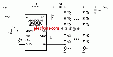
Figure 1. This schematic illustrates the application of a typical LED-backlight driver.
If you disconnect the LED array from the IC, the loss of LED current in RFB allows the voltage at FB (pin 6) to drop below the internal current-controller threshold, causing the device to begin increasing its output voltage. Unfortunately, the MAX1698 (like many similar devices) cannot sense the disconnected-LED condition, so its output voltage increases to a level that can destroy the external MOSFET and Schottky diode. This problem is present for any boost converter; not just LED drivers.
The simplest solution is a zener diode connected across the LEDs (Figure 2). A 16V zener works fine in this case (the four white LEDs drop about 12V), but it must be capable of dissipating power. When the LEDs are drawing 100mA or more and someone disconnects them, the zener must dissipate ~1/6W. A possible alternative to this circuit is shown in Figure 3.

Figure 2. The simplest protection for the Figure 1 circuit adds just a zener diode.
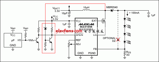
Figure 3. Adding a zener diode and transistor to the Figure 1 circuit provides low-power protection for the MOSFET and Schottky diode.
It requires the addition of two resistors and one transistor, but the Figure 3 circuit doesn’t dissipate extra power when the LEDs are disconnected. It also saves space—the zener can be a 0.5W device, and the resistor and BJT can be standard low-power devices available in small packages like the SOT23-3, or smaller. The circuit senses output voltage at the MOSFET drain, and deactivates the driver (MAX1698) by controlling its Shutdown input. You can choose a zener voltage that ensures this voltage is within the MOSFET’s operating characteristics.
In other words, the circuit doesn’t "work" except when a user removes the LED array. In that event the output voltage starts to rise, and when it reaches the zener voltage the circuit trips and shuts down the IC. As in shutdown mode, the inductor begins to discharge when the driver turns off the external MOSFET, which allows the output voltage to drop below the zener voltage and bring the driver out of shutdown. The driver re-starts, and if the LED array remains unconnected, the output voltage increases until it exceeds the zener voltage, and triggers the protection again.
Because the output voltage regulates around the zener voltage, this circuit does not generate a damaging current spike when the LED array is reconnected. To save battery energy, it also permits external control of the shutdown mode (using a microcontroller, for instance, as shown in Figure 3), to switch off the backlight array.
Another alternative is the circuit of Figure 4, which requires an additional comparator and three resistors. This approach also uses small, low-cost components and dissipates negligible power. It senses output voltage at the Schottky-diode cathode, and limits circuit operation to a voltage set by the resistor divider and the driver’s VREF output (1.25V typical).
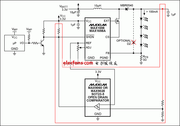
Figure 4. Better yet, this tiny comparator protects the Figure 1 circuit, dissipates little power, and requires little space on the pc board.
This protection circuit remains inactive until the LED array is removed, and (again) its operating voltages remain well within limits for the chosen MOSFET. The comparator should have an open-drain output (MAX9060/MAX9061 or MAX9028) to permit external control of the shutdown mode by a microcontroller—as before, to switch off the backlight array when needed.
The circuit also consumes less power, according to values selected for the resistor divider. (Its quiescent current is a few tens of microamps.) Last but not least, this circuit is smaller than the other two because the comparator comes in a tiny SOT23-5 package (MAX9060/MAX9061) or 1×1.52mm UCSP™ package (MAX9028). All three circuits protect the external MOSFET and diode in an LED-backlight application, when the LED array is disconnected.
UCSP is a trademark of Maxim Integrated Products, Inc.

