最近刚触摸MPLABX集成开发环境,X16和X8编译器,和曾经的PIC的开发环境有了很大的差异,这儿就说一下新建工程的第一步,装备位的编写。
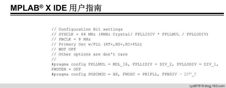
1:MPALB X IDE用户攻略里边比如的装备位写法:
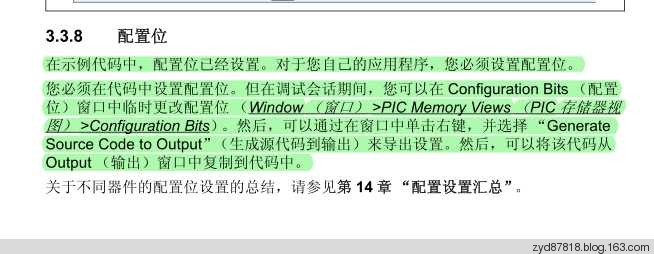
2:依据MPALB X IDE用户攻略里边的描绘,能够主动生成装备位的代码
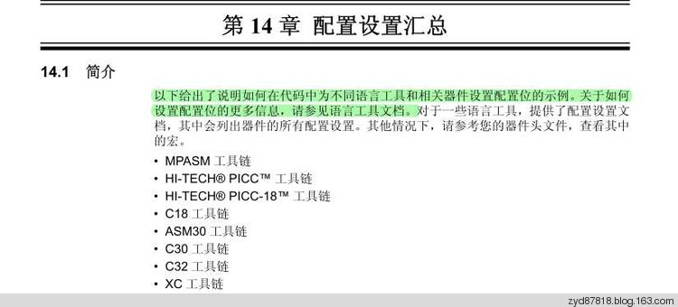
3:依据MPALB X IDE用户攻略,阐明装备位的编写是和编译器相关的,因而咱们看编译器的阐明文档
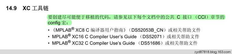
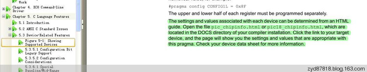
4:依据X8编译器的阐明文档,看编译器装置目录下的文档阐明
5:下面便是编译器装置目录下的文档阐明
16F877A Support Information
#pragma config Usage
#pragma config =
For example:
// Brown-out Reset Enable bit: BOR disabled
// Data EEPROM Memory Code Protection bit: Data EEPROM code protection off
// In-Circuit Debugger Mode bit: In-Circuit Debugger disabled, RB6 and RB7 are general purpose I/O pins
// Flash Program Memory Write Enable bits: Write protection off; all program memory may be written to by EECON control
// Oscillator Selection bits: XT oscillator
// Watchdog Timer Enable bit: WDT disabled
// Flash Program Memory Code Protection bit: Code protection off
// Low-Voltage (Single-Supply) In-Circuit Serial Programming Enable bit: RB3 is digital I/O, HV on MCLR must be used for programming
// Power-up Timer Enable bit: PWRT disabled
#pragma config BOREN = OFF, CPD = OFF, DEBUG = OFF, WRT = OFF, FOSC = XT, WDTE = OFF, CP = OFF, LVP = OFF, PWRTE = OFF
#pragma config =
For example:
// Brown-out Reset Enable bit: BOR disabled
// Data EEPROM Memory Code Protection bit: Data EEPROM code protection off
// In-Circuit Debugger Mode bit: In-Circuit Debugger disabled, RB6 and RB7 are general purpose I/O pins
// Flash Program Memory Write Enable bits: Write protection off; all program memory may be written to by EECON control
// Oscillator Selection bits: XT oscillator
// Watchdog Timer Enable bit: WDT disabled
// Flash Program Memory Code Protection bit: Code protection off
// Low-Voltage (Single-Supply) In-Circuit Serial Programming Enable bit: RB3 is digital I/O, HV on MCLR must be used for programming
// Power-up Timer Enable bit: PWRT disabled
#pragma config BOREN = 0x0, CPD = 0x1, DEBUG = 0x1, WRT = 0x3, FOSC = 0x1, WDTE = 0x0, CP = 0x1, LVP = 0x0, PWRTE = 0x1
#pragma config =
For example:
// Brown-out Reset Enable bit: BOR disabled
// Data EEPROM Memory Code Protection bit: Data EEPROM code protection off
// In-Circuit Debugger Mode bit: In-Circuit Debugger disabled, RB6 and RB7 are general purpose I/O pins
// Flash Program Memory Write Enable bits: Write protection off; all program memory may be written to by EECON control
// Oscillator Selection bits: XT oscillator
// Watchdog Timer Enable bit: WDT disabled
// Flash Program Memory Code Protection bit: Code protection off
// Low-Voltage (Single-Supply) In-Circuit Serial Programming Enable bit: RB3 is digital I/O, HV on MCLR must be used for programming
// Power-up Timer Enable bit: PWRT disabled
#pragma config CONFIG = 0xFF39
For example:
// IDLOC @ 0x2000
#pragma config IDLOC0 = 0x3FFF
#pragma config Settings
Register: CONFIG @ 0x2007
| BOREN = |
Brown-out Reset Enable bit |
| OFF |
BOR disabled |
| ON |
BOR enabled |
| CPD = |
Data EEPROM Memory Code Protection bit |
| OFF |
Data EEPROM code protection off |
| ON |
Data EEPROM code-protected |
| DEBUG = |
In-Circuit Debugger Mode bit |
| OFF |
In-Circuit Debugger disabled, RB6 and RB7 are general purpose I/O pins |
| ON |
In-Circuit Debugger enabled, RB6 and RB7 are dedicated to the debugger |
| WRT = |
Flash Program Memory Write Enable bits |
| OFF |
Write protection off; all program memory may be written to by EECON control |
| HALF |
0000h to 0FFFh write-protected; 1000h to 1FFFh may be written to by EECON control |
| 1FOURTH |
0000h to 07FFh write-protected; 0800h to 1FFFh may be written to by EECON control |
| 256 |
0000h to 00FFh write-protected; 0100h to 1FFFh may be written to by EECON control |
| FOSC = |
Oscillator Selection bits |
| XT |
XT oscillator |
| LP |
LP oscillator |
| EXTRC |
RC oscillator |
| HS |
HS oscillator |
| WDTE = |
Watchdog Timer Enable bit |
| OFF |
WDT disabled |
| ON |
WDT enabled |
| CP = |
Flash Program Memory Code Protection bit |
| OFF |
Code protection off |
| ON |
All program memory code-protected |
| LVP = |
Low-Voltage (Single-Supply) In-Circuit Serial Programming Enable bit |
| OFF |
RB3 is digital I/O, HV on MCLR must be used for programming |
| ON |
RB3/PGM pin has PGM function; low-voltage programming enabled |
| PWRTE = |
Power-up Timer Enable bit |
| OFF |
PWRT disabled |
| ON |
PWRT enabled |
Register: IDLOC0 @ 0x2000
Register: IDLOC1 @ 0x2001
Register: IDLOC2 @ 0x2002
Register: IDLOC3 @ 0x2003
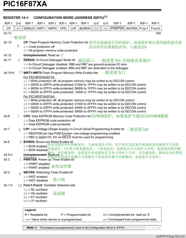
装备位的大约阐明:
总结:咱们能够依据编译器的文档阐明来自己编写装备位,也能够运用IDE来主动生成。引荐运用主动生成的装备位代码。
声明:本文内容来自网络转载或用户投稿,文章版权归原作者和原出处所有。文中观点,不代表本站立场。若有侵权请联系本站删除(kf@86ic.com)https://www.86ic.net/xinpin/320091.html