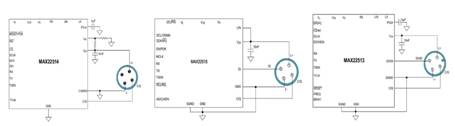
根据PCM2702的USB声卡原理图及电路图

Make a sound card is no more a complex issue. If you use great %&&&&&% PCM2702 from BURR BROWN / Texas Instruments you can create a fully functional USB sound card. This sound card can be powered from USB port and has one stereo output. You don’t need to install any driver for Windows XP and Vista, because they are already inside. This is really plug and play.
Few months ago I have seen USB sound card called Alien DAC. The construction on the project web page inspired me to build this thing also.
The core of this construction is 16-Bit Stereo Digital-To-Analog Convertor with USB interface PCM2702.
PCM2702 needs only few additional parts to work. The schematic is not complex. Sound card can be powered directly from USB port (jumper W1) or from external power supply (jumper W3). PCM2702 needs two power supply 3.3V (3V-3.6V) and 5V (4.5V-5.5V). I used fixed output voltage LDO TPS76733Q for 3.3V (IO2) and adjustable output voltage LDO TPS76701Q for 5V (IO3). Both LDO are produced by TI, I used this because I had it in my drawer. Any similar LDO can be used. Output voltage of IO3 should be set to little bit lower than input voltage to allow LDO good stabilization, in my case output voltage is set to 4.8V. Output voltage can be set by adjustable resistor R33. In case of low power supply, IO3 can be shorted by jumper W3. LED D3 signalizes power on.
Small ferrite beads are placed before all power pins of PCM2702 and in Vbus and GND of USB. These small beads reduce high frequency hum. I had a problem find this small SMD ferrite beads in local stores but finally I acquire few of them from old hard drive. They are not absolutely necessary, you can use zero ohm resistors instead of them.
Low-pass filter is placed in output signal path to reduce sampling frequency. An OPA2353UA dual op amp is configured as a stereo 2nd-order low-pass filter. Led diode D1 is illuminated when PCM2702 plays audio data received from the USB bus. Led diode D2 is illuminated when USB bus suspends audio data transmission to the PCM2702.
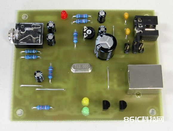
PCB图:

PCB assembly diagram
PCB – Download PCB in [EPS format] or [%&&&&&% format]
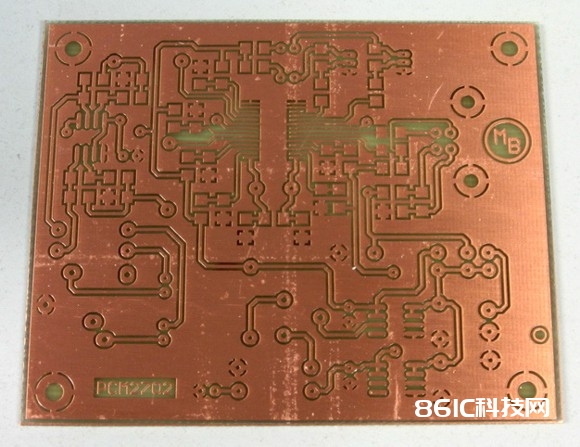
Bottom side of PCB (single side PCB, made by standard etching method)

Assembled bottom side
Conclusion
This circuit works very well. I only shorted crystal during soldering so the circuit didn’t work, but after removing the short the sound card started to work. I have tested in Windows 2000, XP and Vista. It works in all mentioned systems. Drivers are present in operation system so the sound card is ready in few seconds after you connect it.
During writing this article I have found that PCM2702 is now not recommended for new design, but TI offer even better solution. PCM2704, PCM2705 have same functionality as PCM2702, but they include output filter. They are able to drive directly headphones. Volume and Mute can be controlled through SPI bus in PCM2705 or with pushbuttons in case of PCM2704. PCM2704 and PCM2705 are in TSSOP28 package. PCM2706 is similar to PCM2704 and PCM2707 to PCM2705 but in addition they have I2S bus. PCM2706 and PCM2707 are in TQFP32 package. I recommend using these new chips for new design (look at the TI web page).