所谓间断便是CPU在履行程序的进程中,呈现了某些突发事情时,有必要暂停当时正在履行的程序,转而去处理突发事情,处理完结后,CPU接着履行被暂停的程序。实际上,有许多Linux的驱动都是经过间断的办法来进行内核和硬件的交互。间断机制供给了硬件和软件之间异步传递信息的办法。硬件设备在发生某个事情时经过间断告诉软件进行处理。间断完结了硬件设备按需取得处理器重视的机制,与查询办法比较能够大大节约CPU资源的开支。
1.间断向量表
每个间断都对应一段间断服务程序。当间断发生时,处理器就履行该间断对应的服务程序,完结该间断所要求完结的使命。处理器怎么找到对应的间断服务程序呢?这就需求读取处理器的间断向量表。
间断向量表其实就对应了体系的一段存储区,它依照必定规则存储了处理器中一切不同类型间断的服务程序进口地址(又称间断向量)。S3C2410是依据ARM920T核,ARM920T的间断向量表有两种寄存办法,一种是低端寄存(从0x00000000处开端寄存),另一种是高端寄存(从0xfff000000处开端寄存)。ARM920T能处理8个类型的间断,他们别离是:
>Reset:当处理器的复位电平有用时,发生复位反常,程序跳转到复位处理程序履行。
>Undefined instruction:当处理器遇到不能处理的指令时发生未界说指令间断。
>Software Interrupt:履行SWI(软件间断)指令时发生,可用于用户完结体系调用
>Abort (prefetch):当处理器预取指令的地址不存在或该地址不允许当时指令拜访时,存储器会向处理器宣布间断信号,但当预取的指令被履行时,才会发生指令预取间断。
>Abort (data):当处理器拜访的指令地址不存在或该地址不允许当时指令拜访时,发生数据间断间断。
>Reserved:保存。
>IRQ:当处理器的外部间断恳求引脚有用,且CPSR的I位为0时发生IRQ间断。
>FIQ:当处理器的快速间断恳求引脚有用,且CPSR的F位为0时发生FIQ间断。
对应的间断向量表如表1-1所示。
|
间断类型 |
间断向量(进口地址) |
|
Reset |
0x00000000 |
|
Undefined instruction |
0x00000004 |
|
Software Interrupt |
0x00000008 |
|
Abort (prefetch) |
0x0000000C |
|
Abort (data) |
0x00000010 |
|
Reserved |
0x00000014 |
|
IRQ |
0x00000018 |
|
FIQ |
0x0000001C |
表1-1间断向量表
一般状况下,在每个进口地址处都寄存了一条跳转指令,咱们知道Uboot是用来完结体系的发动加载进程的,在u-boot的/cpu/start.S文件中,就有“b reset”指令,放在0x00000000地址。体系上电今后,CPU将会从0x00000000处得这条指令履行,履行完今后,CPU会跳转到reset标识的代码段去履行处理器复位程序。相同,在体系运转进程中,每逢有间断发生,CPU会依据间断类型(用间断号标识),从内存的0x00000000处开端查表做相应的处理。比方体系触发了一个IRQ间断,IRQ为第6号间断,则CPU将把PC指向0x00000018地址(4*6=24= 0x00000018)处运转,该地址的指令是跳转到“IRQ间断服务程序”处运转。
S3C2410间断源,如图1-1间断源所示:
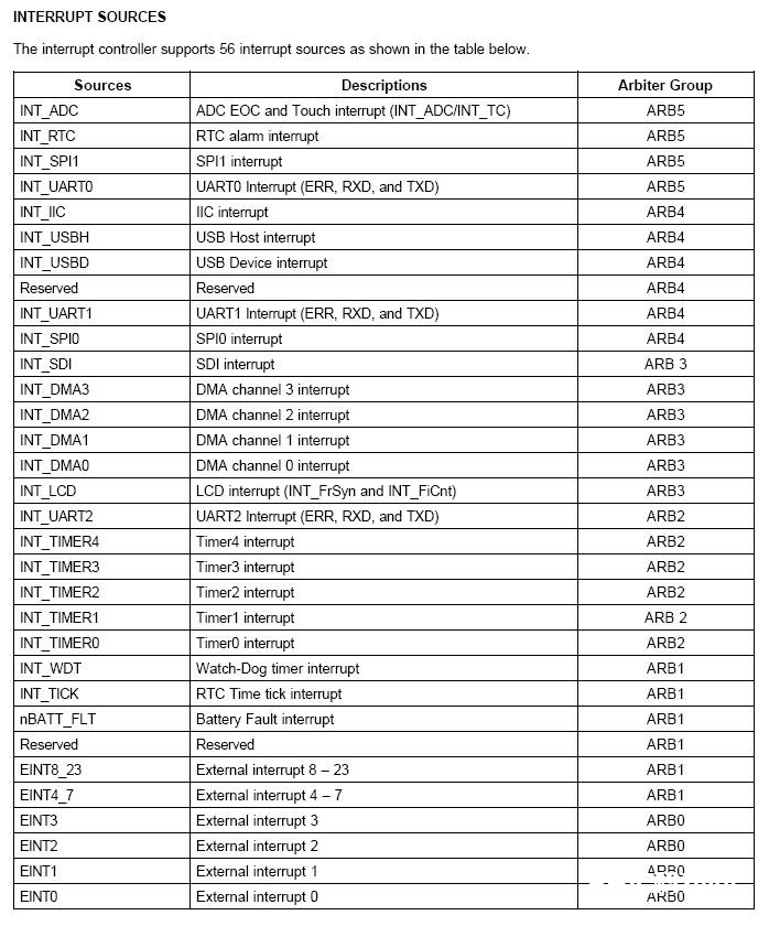
图1-1间断源
INTERRUPT CONTROLLER OPERATION
F-bit and I-bit of Program Status Register (PSR)
If the F-bit of PSR in ARM920T CPU is set to 1, the CPU does not accept the Fast Interrupt Request (FIQ) from the interrupt controller. Likewise, If I-bit of the PSR is set to 1, the CPU does not accept the Interrupt Request (IRQ) from the interrupt controller. So, the interrupt controller can receive interrupts by clearing F-bit or I-bit of the PSR to 0 and setting the corresponding bit of INTMSK to 0.
Interrupt Mode
The ARM920T has two types of Interrupt mode: FIQ or IRQ. All the interrupt sources determine which mode is used at interrupt request.
Interrupt Pending Register
The S3C2410A has two interrupt pending resisters: source pending register (SRCPND) and interrupt pending register (INTPND). These pending registers indicate whether or not an interrupt request is pending. When the interrupt sources request interrupt service, the corresponding bits of SRCPND register are set to 1, and at the same time, only one bit of the INTPND register is set to 1 automatically after arbitration procedure. If interrupts are masked, the corresponding bits of the SRCPND register are set to 1. This does not cause the bit of INTPND register changed. When a pending bit of the INTPND register is set, the interrupt service routine starts whenever the I-flag or F-flag is cleared to 0. The SRCPND and INTPND registers can be read and written, so the service routine must clear the pending condition by writing a 1 to the corresponding bit in the SRCPND register first and then clear the pending condition in the INTPND registers by using the same method.
Interrupt Mask Register
This register indicates that an interrupt has been disabled if the corresponding mask bit is set to 1. If an interrupt mask bit of INTMSK is 0, the interrupt will be serviced normally. If the corresponding mask bit is 1 and the interrupt is generated, the source pending bit will be set.
S3C2410的间断操控器原理如图1-2所示。
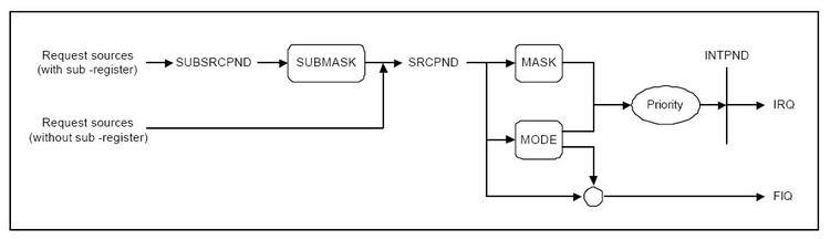
图1-2间断操控器原理
由上图能够看出S3C2410的间断操控器首要经过几个操控寄存器来完结:间断源待决寄存器(Source Pending Register,SRCPND/SUBSRCPND)、间断形式寄存器(Interrupt Mode Register,INTMOD)、间断屏蔽寄存器(Interrupt Mask Register,INTMASK/INTSUBMSK)、间断优先级操控寄存器(IRQ PRIORITY Control Register,PRIORITY)、间断待决寄存器(Interrupt Pending Register,INTPND)。
该图也显现了S3C2410的间断处理流程:首要要有间断源发生间断,这儿面有两条途径标明间断源,上面一条是次级间断源,当次级间断发生后,首要在SUBSRCPND寄存器中挂号,然后经过次级屏蔽寄存器(SUBMASK)来决议这个次级间断源所发生的间断是否被屏蔽掉,被屏蔽掉的间断将不会被履行。次级间断源所发生的间断在经过SUBMASK之后将会与主间断源所发生的间断集合,然后在SRCPND寄存器中挂号,再经过主屏蔽寄存器,得出该间断是否被送往CPU处理的决议。当然,在送往CPU处理之前,还要依据间断形式寄存器的设置判别一下该间断是归于IRQ间断仍是FIQ间断,假如是FIQ间断则直接触发。假如是IRQ间断,则还要判别间断的优先等级,等级高的先履行。
(1)间断源待决寄存器SRCPND/ SUBSRCPND
这两个寄存器在功用上是相同的,它们是间断源待决寄存器。在一个间断处理流程中,间断信号传进间断操控器后首要遇到的便是SRCPND/ SUBSRCPND,这两个寄存器的效果是用于标示出哪个间断恳求被触发。SRCPND的有用位为32,SUBSRCPND的有用位为11,它们中的每一位别离代表一个间断源。SRCPND为主间断源待决寄存器,SUBSRCPND为次间断源待决寄存器。
The SRCPND register is composed of 32 bits each of which is related to an interrupt source. Each bit is set to 1 if the corresponding interrupt source generates the interrupt request and waits for the interrupt to be serviced. Accordingly, this register indicates which interrupt source is waiting for the request to be serviced. Note that each bit of the SRCPND register is automatically set by the interrupt sources regardless of the masking bits in the INTMASK register. In addition, the SRCPND register is not affected by the priority logic of interrupt controller.
In the interrupt service routine for a specific interrupt source, the corresponding bit of the SRCPND register has to be cleared to get the interrupt request from the same source correctly. If you return from the ISR without clearing the bit, the interrupt controller operates as if another interrupt request came in from the same source. In other words, if a specific bit of the SRCPND register is set to 1, it is always considered as a valid interrupt request waiting to be serviced.
The time to clear the corresponding bit depends on the users requirement. If you want to receive another valid request from the same source, you should clear the corresponding bit first, and then enable the interrupt.
You can clear a specific bit of the SRCPND register by writing a data to this register.It clears only the bit positions of the SRCPND corresponding to those set to one in the data. The bit positions corresponding tothose that are set to 0 in the data remains as they are.
SRCPND的各个位信息如表1-3所示。
|
SRCPND |
BIT |
描绘 |
|
INT_ADC |
[31] |
0:Not requested,1:Requested |
|
INT_RTC |
[30] |
0:Not requested,1:Requested |
|
INT_SPI1 |
[29] |
0:Not requested,1:Requested |
|
INT_UART0 |
[28] |
0:Not requested,1:Requested |
|
INT_IIC |
[27] |
0:Not requested,1:Requested |
|
INT_USBH |
[26] |
0:Not requested,1:Requested |
|
INT_USBD |
[25] |
0:Not requested,1:Requested |
|
Reserved |
[24] |
Not used |
|
INT_UART1 |
[23] |
0:Not requested,1:Requested |
|
INT_SPI0 |
[22] |
0:Not requested,1:Requested |
|
INT_SDI |
[21] |
0:Not requested,1:Requested |
|
INT_DMA3 |
[20] |
0:Not requested,1:Requested |
|
INT_DMA2 |
[19] |
0:Not requested,1:Requested |
|
INT_DMA1 |
[18] |
0:Not requested,1:Requested |
|
INT_DMA0 |
[17] |
0:Not requested,1:Requested |
|
INT_LCD |
[16] |
0:Not requested,1:Requested |
|
INT_UART2 |
[15] |
0:Not requested,1:Requested |
|
INT_TIMER4 |
[14] |
0:Not requested,1:Requested |
|
INT_TIMER3 |
[13] |
0:Not requested,1:Requested |
|
INT_TIMER2 |
[12] |
0:Not requested,1:Requested |
|
INT_TIMER1 |
[11] |
0:Not requested,1:Requested |
|
INT_TIMER0 |
[10] |
0:Not requested,1:Requested |
|
INT_WDT |
[9] |
0:Not requested,1:Requested |
|
INT_TICK |
[8] |
Reserved |
|
INT_BATT_FLT |
[7] |
0:Not requested,1:Requested |
|
Reserved |
[6] |
Reserved |
|
INT_EINT8_23 |
[5] |
0:Not requested,1:Requested |
|
INT_EINT4_7 |
[4] |
0:Not requested,1:Requested |
|
INT_EINT3 |
[3] |
0:Not requested,1:Requested |
|
INT_EINT2 |
[2] |
0:Not requested,1:Requested |
|
INT_EINT1 |
[1] |
0:Not requested,1:Requested |
|
INT_EINT0 |
[0] |
0:Not requested,1:Requested |
表1-3 SRCPND各位信息
SRCPN寄存器中每个位的初始值皆为0。假定现在体系触发了EINT0间断,则第0位将被置1,代表EINT0间断被触发,该间断恳求行将被处理(若该间断没有被屏蔽的话)。SUBSRCPND状况与SRCPND相同,如表1-4所示。
|
Reserved |
[31:11] |
0:Not requested,1:Requested |
|
INT_ADC |
[10] |
0:Not requested,1:Requested |
|
INT_TC |
[9] |
0:Not requested,1:Requested |
|
INT_ERR2 |
[8] |
0:Not requested,1:Requested |
|
INT_TXD2 |
[7] |
0:Not requested,1:Requested |
|
INT_RXD2 |
[6] |
0:Not requested,1:Requested |
|
INT_ERR1 |
[5] |
0:Not requested,1:Requested |
|
INT_TXD1 |
[4] |
0:Not requested,1:Requested |
|
INT_RXD1 |
[3] |
0:Not requested,1:Requested |
|
INT_ERR0 |
[2] |
0:Not requested,1:Requested |
|
INT_TXD0 |
[1] |
0:Not requested,1:Requested |
|
INT_RXD0 |
[0] |
0:Not requested,1:Requested |
表1-4 SUBSRCPND各位信息
(2)间断形式寄存器INTMOD
该寄存器用来指定间断源处理形式(IRQ仍是FIQ),有用位为32位,每一位与SRCPND中各位相对应,若某位为0,则该位相对应的间断按IRQ形式处理,为1则以FIQ形式进行处理,该寄存器初始化值为0x00000000,即一切间断皆以IRQ形式进行处理。如表1-5所示。
This register is composed of 32 bits each of which is related to an interrupt source. If a specific bit is set to 1, the corresponding interrupt is processed in the FIQ (fast interrupt) mode. Otherwise, it is processed in the IRQ mode (normal interrupt).
Note that only one interrupt source can be serviced in the FIQ mode in the interrupt controller (you should use the FIQ mode only for the urgent interrupt). Thus,only one bit of INTMOD can be set to 1.
|
寄存器 |
地址 |
描绘 |
|
INTMOD |
0X4A000004 |
0 = IRQ mode,1=FIQ mode |
表1-5 INTMOD寄存器
NOTE: If an interrupt mode is set to FIQ mode in the INTMOD register, FIQ interrupt will not affect both INTPND and INTOFFSET registers. In this case, the two registers are valid only for IRQ mode interrupt source.
(3)间断屏蔽寄存器INTMSK/ INTSUBMSK
This register also has 32 bits each of which is related to an interrupt source. If a specific bit is set to 1, the CPU does not service the interrupt request from the corresponding interrupt source (note that even in such a case, the corresponding bit of SRCPND register is set to 1). If the mask bit is 0, the interrupt request can be serviced.
INTMSK为主间断屏蔽寄存器,INTSUBMSK为次间断屏蔽寄存器。INTMSK有用位为32,INTSUBMSK有用位为11,这两个寄存器各个位与SRCPND和SUBSRCPND别离对应。它们的效果是决议该位相应的间断恳求是否被处理。若某位被设置为1,则该位相对应的间断发生后将被疏忽(CPU不处理该间断恳求),设置为0则对其进行处理。这两个寄存器初始化后的值是0xFFFFFFFF和0x7FF,既默许状况下一切的间断都是被屏蔽的。如表1-6所示。
|
寄存器 |
地址 |
描绘 |
|
INTMSK |
0X4A000008 |
0 =Interrupt service is available, 1= Interrupt service is masked |
表1-6INTMSK寄存器
(4)PRIORITY寄存器
一个嵌入式体系一般有多个间断恳求源。当多个间断源一起恳求间断时,就会存在CPU应该优先呼应哪个间断恳求源的问题,假如处理不妥将会引起紊乱,导致体系不能正常作业。一般处理这个问题的办法是依据间断源事情的轻重缓急规则间断源的优先级,CPU优先呼应间断优先级高的间断恳求。
S3C2410的优先级判别分为两级。如图1-3所示,SRCPND寄存器对应的32个间断源一共被分为6个组,每个组由一个ARBITER(0~5)寄存器对其进行办理。间断有必要先由所属组的ARBITER(0~5)进行榜首次优先级判别(榜首级判别)后再发往ARBITER6进行终究的判别(第二级判别)。ARBITER(0~5)这六个组的优先级现已固定,由ARBITER0操控的组优先级最高,其次是ARBITER1, ARBITER2, ARBITER3, ARBITER4, ARBITER5。可是每个组中的各个间断的优先级是能够操控的,咱们只需求设置PRIORITY的相应位。
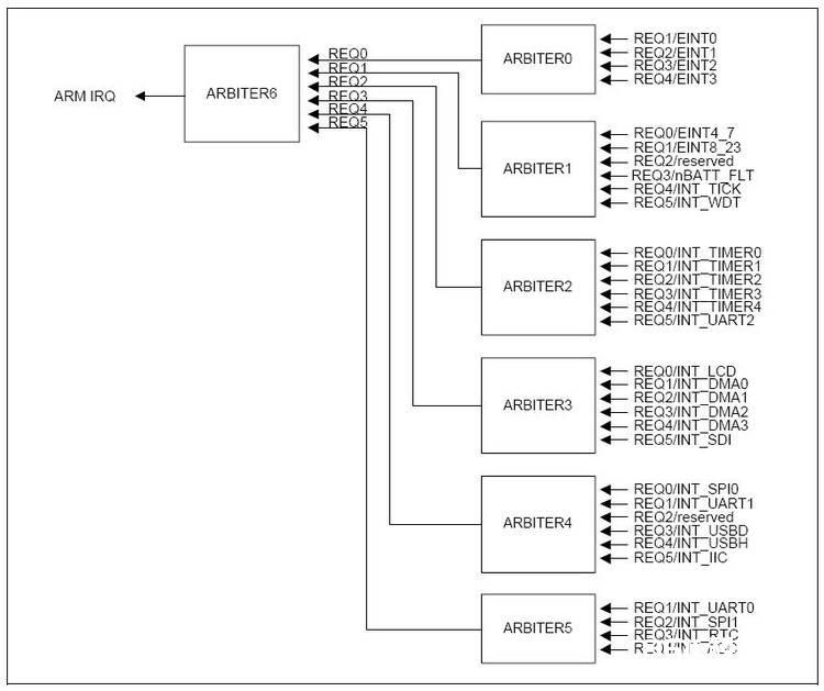
图1-3 Priority Generating Block
INTERRUPT PRIORITY
Each arbiter can handle six interrupt requests based on the one bit arbiter mode control (ARB_MODE) and two bits of selection control signals (ARB_SEL) as follows:
— If ARB_SEL bits are 00b, the priority order is REQ0, REQ1, REQ2, REQ3, REQ4, and REQ5.
— If ARB_SEL bits are 01b, the priority order is REQ0, REQ2, REQ3, REQ4, REQ1, and REQ5.
— If ARB_SEL bits are 10b, the priority order is REQ0, REQ3, REQ4, REQ1, REQ2, and REQ5.
— If ARB_SEL bits are 11b, the priority order is REQ0, REQ4, REQ1, REQ2, REQ3, and REQ5.
Note that REQ0 of an arbiter always has the highest priority, and REQ5 has the lowest one. In addition, by changing the ARB_SEL bits, we can rotate the priority of REQ1 to REQ4.
Here,if ARB_MODE bit is set to 0, ARB_SEL bits are not automatically changed, making the arbiter to operate in the fixed priority mode (note that even in this mode, we can reconfigure the priority by manually changing the ARB_SEL bits). On the other hand, if ARB_MODE bit is 1, ARB_SEL bits are changed in rotation fashion, e.g., if REQ1 is serviced, ARB_SEL bits are changed to 01b automatically so as to put REQ1 into the lowest priority. The detailed rules of ARB_SEL change are as follows:
— If REQ0 or REQ5 is serviced, ARB_SEL bits are not changed at all.
— If REQ1 is serviced, ARB_SEL bits are changed to 01b.
— If REQ2 is serviced, ARB_SEL bits are changed to 10b.
— If REQ3 is serviced, ARB_SEL bits are changed to 11b.
— If REQ4 is serviced, ARB_SEL bits are changed to 00b.
|
PRIORITY |
BIT |
描绘 |
|
ARB_SEL6 |
[20:19] |
Arbiter 6 group priority order set 00:REQ 0-1-2-3-4-5,01:REQ 0-2-3-4-1-5 10:REQ 0-3-4-1-2-5,11:REQ 0-4-1-2-3-5 |
|
ARB_SEL5 |
[18:17] |
Arbiter 5 group priority order set 00:REQ 0-1-2-3-4-5,01:REQ 0-2-3-4-1-5 10:REQ 0-3-4-1-2-5,11:REQ 0-4-1-2-3-5 |
|
ARB_SEL4 |
[16:15] |
Arbiter 4 group priority order set 00:REQ 0-1-2-3-4-5,01:REQ 0-2-3-4-1-5 10:REQ 0-3-4-1-2-5,11:REQ 0-4-1-2-3-5 |
|
ARB_SEL3 |
[14:13] |
Arbiter 3 group priority order set 00:REQ 0-1-2-3-4-5,01:REQ 0-2-3-4-1-5 10:REQ 0-3-4-1-2-5,11:REQ 0-4-1-2-3-5 |
|
ARB_SEL2 |
[12:11] |
Arbiter 2 group priority order set 00:REQ 0-1-2-3-4-5,01:REQ 0-2-3-4-1-5 10:REQ 0-3-4-1-2-5,11:REQ 0-4-1-2-3-5 |
|
ARB_SEL1 |
[10:9] |
Arbiter 1 group priority order set 00:REQ 0-1-2-3-4-5,01:REQ 0-2-3-4-1-5 10:REQ 0-3-4-1-2-5,11:REQ 0-4-1-2-3-5 |
|
ARB_SEL0 |
[8:7] |
Arbiter 0 group priority order set 00:REQ 1-2-3-4,01:REQ 2-3-4-1 10:REQ 3-4-1-2,11:REQ 4-1-2-3 |
|
ARB_MODE6 |
[6] |
Arbiter 6 group priority rotate enable 0:Priority does not rotate,1:Priority rotate enable |
|
ARB_MODE5 |
[5] |
Arbiter 5 group priority rotate enable 0:Priority does not rotate,1:Priority rotate enable |
|
ARB_MODE4 |
[4] |
Arbiter 4 group priority rotate enable 0:Priority does not rotate,1:Priority rotate enable |
|
ARB_MODE3 |
[3] |
Arbiter 3 group priority rotate enable 0:Priority does not rotate,1:Priority rotate enable |
|
ARB_MODE2 |
[2] |
Arbiter 2 group priority rotate enable 0:Priority does not rotate,1:Priority rotate enable |
|
ARB_MODE1 |
[1] |
Arbiter 1 group priority rotate enable 0:Priority does not rotate,1:Priority rotate enable |
|
ARB_MODE0 |
[0] |
Arbiter 0 group priority rotate enable 0:Priority does not rotate,1:Priority rotate enable |
表1-7 PRIORITY寄存器
表1-7是PRIORITY寄存器各个位的参数表。从表上咱们能够知道PRIORITY寄存器内部各个位被分为两种类型,一种是ARB_MODE,另一种为ARB_SEL, ARB_MODE类型有5组,别离对应ARBITER(2~6),ARB_SEL类型有7组,别离对应ARBITER(0~6)。
以ARBITER2为例,咱们来看一下PRIORITY寄存器中ARB_SEL, ARB_MODE之间的相互关系。首要咱们看到ARBITER2寄存器办理的该组间断里包含了6个间断,别离是INT_TIMER0,INT_TIMER1,INT_TIMER2,INT_TIMER3,INT_TIMER4,INT_UART2,它们的默许间断恳求号别离为REQ0,REQ1,REQ2,REQ3,REQ4,REQ5。咱们先看PRIORITY寄存器中的ARB_SEL2,该参数由两个位组成,初始值为00。从该表能够看出00界说了一个次第0-1-2-3-4-5,这个次第便是这组间断组的优先级摆放,这个次第指明晰以间断恳求号为0(REQ0)的INT_TIMER0具有最高的间断优先级,其次是INT_TIMER1,INT_TIMER2…。假定现在ARB_SEL2的值被咱们设置为01。则一个新的优先级次第将被运用,01对应的优先级次第为0-2-3-4-1-5,从中能够看出优先级最高和最低的间断恳求和之前没有改变,但原本处于第2优先级的INT_TIMER1间断现在变成了第5优先级。从ARB_SEL2被设置为00,01,10,11各个值所呈现的状况能够看出,除了最高和最低的优先级不变以外,其他各个间断的优先级其实是在做一个旋转摆放(rotate)。为了到达对各个间断相等对待这一方针,咱们能够让优先级次第在每个间断恳求被处理完之后主动进行一次旋转,怎么主动让它旋转呢?咱们能够经过设置ARB_MODE2位到达这个意图,该方位1代表敞开对应间断组的优先级次第主动旋转,0则为封闭,按固定的次第摆放优先级列表。
(5)间断待决寄存器INTPND
Each of the 32 bits in the interrupt pending register shows whether the corresponding interrupt request, which is unmasked and waits for the interrupt to be serviced, has the highest priority .Since the INTPND register is located after the priority logic, only one bit can be set to 1, and that interrupt request generates IRQ to CPU.In interrupt service routine for IRQ, you can read this register to determine which interrupt source is serviced among the 32 sources.
Like the SRCPND register,this register has to be cleared in the interrupt service routine after clearing the SRCPND register. We can clear a specific bit of the INTPND register by writing a data to this register.It clears only the bit positions of the INTPND register corresponding to those set to one in the data. The bit positions corresponding to those that are set to 0 in the data remains as they are.
INTPND的具体信息如表1-8所示:
|
INTPND |
BIT |
描绘 |
|
INT_ADC |
[31] |
0:Not requested,1:Requested |
|
INT_RTC |
[30] |
0:Not requested,1:Requested |
|
INT_SPI1 |
[29] |
0:Not requested,1:Requested |
|
INT_UART0 |
[28] |
0:Not requested,1:Requested |
|
INT_IIC |
[27] |
0:Not requested,1:Requested |
|
INT_USBH |
[26] |
0:Not requested,1:Requested |
|
INT_USBD |
[25] |
0:Not requested,1:Requested |
|
Reserved |
[24] |
Not used |
|
INT_UART1 |
[23] |
0:Not requested,1:Requested |
|
INT_SPI0 |
[22] |
0:Not requested,1:Requested |
|
INT_SDI |
[21] |
0:Not requested,1:Requested |
|
INT_DMA3 |
[20] |
0:Not requested,1:Requested |
|
INT_DMA2 |
[19] |
0:Not requested,1:Requested |
|
INT_DMA1 |
[18] |
0:Not requested,1:Requested |
|
INT_DMA0 |
[17] |
0:Not requested,1:Requested |
|
INT_LCD |
[16] |
0:Not requested,1:Requested |
|
INT_UART2 |
[15] |
0:Not requested,1:Requested |
|
INT_TIMER4 |
[14] |
0:Not requested,1:Requested |
|
INT_TIMER3 |
[13] |
0:Not requested,1:Requested |
|
INT_TIMER2 |
[12] |
0:Not requested,1:Requested |
|
INT_TIMER1 |
[11] |
0:Not requested,1:Requested |
|
INT_TIMER0 |
[10] |
0:Not requested,1:Requested |
|
INT_WDT |
[9] |
0:Not requested,1:Requested |
|
INT_TICK |
[8] |
Reserved |
|
INT_BATT_FLT |
[7] |
0:Not requested,1:Requested |
|
Reserved |
[6] |
Reserved |
|
INT_EINT8_23 |
[5] |
0:Not requested,1:Requested |
|
INT_EINT4_7 |
[4] |
0:Not requested,1:Requested |
|
INT_EINT3 |
[3] |
0:Not requested,1:Requested |
|
INT_EINT2 |
[2] |
0:Not requested,1:Requested |
|
INT_EINT1 |
[1] |
0:Not requested,1:Requested |
|
INT_EINT0 |
[0] |
0:Not requested,1:Requested |
表1-8寄存器INTPND
表1-8是INTPND寄存器各位的具体功用列表。不难发现,INTPND寄存器与SRCPND长得如出一辙,但他们在间断处理中却扮演着不同的人物。INTPND寄存器的每个位对应一个间断恳求,若该位被置1,则标明相应的间断恳求被触发。提到这儿你可能会发现它不只和SRCPND长得如出一辙,就连功用都相同,其实不然,他们在功用上有着严重的差异。SRCPND是间断源待决寄存器,某个位被置1标明相应的间断被触发,但咱们知道在同一时间内体系能够触发若干个间断,只需间断被触发了,SRCPND的相应位便被置1,也便是说SRCPND在同一时间能够有若干位一起被置1,但是INTPND则不同,他在某一时间只能有1个位被置1,INTPND某个位被置1,则标明CPU行将或现已在对该位相应的间断进行处理。所以咱们能够有一个总结:SRCPND说明晰有什么间断被触发了,INTPND说明晰CPU行将或现已在对某一个间断进行处理。
每逢某一个间断被处理完之后,咱们有必要手动将SRCPND/SUBSRCPND , INTPND三个寄存器中与该间断相应的位由1设置为0。
(6)间断偏移寄存器INTOFFSET
INTOFFSET寄存器的功用很简单,它用于标明哪个间断正在被处理。表1-9是该寄存器各位具体功用列表:若当时INT_TIMER0被触发了,则该寄存器的值为10,以此类推。
|
间断源 |
偏移值 |
间断源 |
偏移值 |
|
INT_ADC |
31 |
INT_UART2 |
15 |
|
INT_RTC |
30 |
INT_TIMER4 |
14 |
|
INT_SPI1 |
29 |
INT_TIMER3 |
13 |
|
INT_UART0 |
28 |
INT_TIMER2 |
12 |
|
INT_IIC |
27 |
INT_TIMER1 |
11 |
|
INT_USBH |
26 |
INT_TIMER0 |
10 |
|
INT_USBD |
25 |
INT_WDT |
9 |
|
Reserved |
24 |
INT_T%&&&&&%K |
8 |
|
INT_UART1 |
23 |
INT_BATT_FLT |
7 |
|
INT_SPI0 |
22 |
Reserved |
6 |
|
INT_SDI |
21 |
INT_EINT8_23 |
5 |
|
INT_DMA3 |
20 |
INT_EINT4_7 |
4 |
|
INT_DMA2 |
19 |
INT_EINT3 |
3 |
|
INT_DMA1 |
18 |
INT_EINT2 |
2 |
|
INT_DMA0 |
17 |
INT_EINT1 |
1 |
|
INT_LCD |
16 |
INT_EINT0 |
0 |
表1-9 INTOFFSET寄存器