SRL(移位寄存器)资源,在FPGA中都有,不过是叫不同的姓名。Xilinx FPGA内部的LUT有个特别功用,便是能够装备成可变长度SRL。
5输入的一个LUT能够变成32bit 的SRL
6输入的,能够变成64bit的SRL
所以,你写的SRL或许被综组成LUT。
能够界说移位长度的移位寄存器。
便是用一个lut能够完成16位的移位寄存器。

SRL16 的是 16bit移位寄存器查找表 // 16-Bit Shift Register Look-Up-Table (LUT)
在一个LUT中能够完成16个FF移位的功用!
SSRL16 SRL16_inst (
.Q(Q), // SRL data output
.A0(A0), // Select[0] input
.A1(A1), // Select[1] input
.A2(A2), // Select[2] input
.A3(A3), // Select[3] input
.CLK(CLK), // Clock input
.D(D) // SRL data input
);
Xilinx 官网的阐明——原理
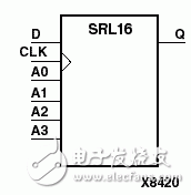
SRL16 is a shift register look up table (LUT)。 The inputs A3, A2, A1, and A0 select the output length of the shift register. The shift register may be of a fixed, staTIc length or it may be dynamically adjusted.
The shift register LUT contents are iniTIalized by assigning a four-digit hexadecimal number to an INIT attribute. The first, or the left-most, hexadecimal digit is the most significant bit. If an INIT value is not specified, it defaults to a value of four zeros (0000) so that the shift register LUT is cleared during configuraTIon.
The data (D) is loaded into the first bit of the shift register during the Low-to-High clock (CLK) transiTIon. During subsequent Low-to-High clock transitions data is shifted to the next highest bit position as new data is loaded. The data appears on the Q output when the shift register length determined by the address inputs is reached.
这儿说了几点,
– 移位寄存器的初始值能够用INIT特点初始化;
– 移位寄存器的长度由地址线的取值决议;
– 移位数据从D端输入,Q端输出
– 先移入的数据是MSB
Xilinx 官网的阐明——Static Length Mode
To get a fixed length shift register, drive the A3 through A0 inputs with static values. The length of the shift register can vary from 1 bit to 16 bits as determined from the following formula:
Length = (8*A3) +(4*A2) + (2*A1) + A0 +1
If A3, A2, A1, and A0 are all zeros (0000), the shift register is one bit long. If they are all ones (1111), it is 16 bits long.
Xilinx 官网的阐明——Dynamic Length Mode
The length of the shift register can be changed dynamically by changing the values driving the A3 through A0 inputs. For example, if A2, A1, and A0 are all ones (111) and A3 toggles between a one (1) and a zero (0), the length of the shift register changes from 16 bits to 8 bits.
Internally, the length of the shift register is always 16 bits and the input lines A3 through A0 select which of the 16 bits reach the output.
Inputs Output
Am CLK D Q
Am X X Q(Am)
Am ↑ D Q(Am-1)
m= 0, 1, 2, 3
这儿提示了几个关键:
– 移位寄存器是可变长度的
– 长度的改动由地址线来指定
– 内部的寄存器长度是不变的,仅仅截取的长度变了
– 数据先移入到A0,然后到A1,以此类推,最终从指定长度的Am-1处输出,比方A=8,则数据从地址0输入,从地址7输出,这样有用的移位长度就为8。
Xilinx 官网的阐明——VHDL例化实例
— SRL16: 16-bit shift register LUT operating on posedge of clock
— All FPGAs
— Xilinx HDL Libraries Guide version 7.1i
SRL16_inst : SRL16
— The following generic declaration is only necessary if you wish to
— change the initial contents of the SRL to anything other than all
— zero‘s.
generic map (
INIT =》 X“0000”)
port map (
Q =》 Q, — SRL data output
A0 =》 A0, — Select[0] input
A1 =》 A1, — Select[1] input
A2 =》 A2, — Select[2] input
A3 =》 A3, — Select[3] input
CLK =》 CLK, — Clock input
D =》 D — SRL data input
);
— End of SRL16_inst instantiation
仿制代码
Xilinx 官网的阐明——Verilog例化实例
— SRL16: 16-bit shift register LUT operating on posedge of clock
– All FPGAs
— Xilinx HDL Libraries Guide version 7.1i
SSRL16 SRL16_inst (
.Q(Q), // SRL data output
.A0(A0), // Select[0] input
.A1(A1), // Select[1] input
.A2(A2), // Select[2] input
.A3(A3), // Select[3] input
.CLK(CLK), // Clock input
.D(D) // SRL data input
);
// The following defparam declaration is only necessary if you wish to
// change the initial contents of the SRL to anything other than all
// zero’s. If the instance name to the SRL is changed, that change
// needs to be reflected in the defparam statements.
defparam SRL16_inst.INIT = 16‘h0000;
// End of SRL16_inst instantiation
然后详细比如:
根据SRL16的分布式RAM不再支撑V5、S6和V6等器材,可是SRL16是一切XIlinx器材都支撑的,并且在规划中使用十分频频,因而可通过调用原语的方法来调用SRL16E乃至SRL32E来完成本来ISE分布式RAM IP核的规划。下面给出一段示例代码
module s2p_8channels_srl16(
a, d, clk, we, qspo
);
input [3:0] a;
input [4:0] d;
input clk;
input we;
output [4:0] qspo;
SRL16E #(
.INIT(16’h0000) // Initial Value of Shift Register
) SRL16_inst_1 (
.Q(qspo[0]), // SRL data output
.A0(a[0]), // Select[0] input
.A1(a[1]), // Select[1] input
.A2(a[2]), // Select[2] input
.A3(a[3]), // Select[3] input
.CE(we),
.CLK(clk), // Clock input
.D(d[0]) // SRL data input
);
SRL16E #(
.INIT(16‘h0000) // Initial Value of Shift Register
) SRL16_inst_2 (
.Q(qspo[1]), // SRL data output
.A0(a[0]), // Select[0] input
.A1(a[1]), // Select[1] input
.A2(a[2]), // Select[2] input
.A3(a[3]), // Select[3] input
.CE(we),
.CLK(clk), // Clock input
.D(d[1]) // SRL data input
);
SRL16E #(
.INIT(16’h0000) // Initial Value of Shift Register
) SRL16_inst_3 (
.Q(qspo[2]), // SRL data output
.A0(a[0]), // Select[0] input
.A1(a[1]), // Select[1] input
.A2(a[2]), // Select[2] input
.A3(a[3]), // Select[3] input
.CE(we),
.CLK(clk), // Clock input
.D(d[2]) // SRL data input
);
SRL16E #(
.INIT(16‘h0000) // Initial Value of Shift Register
) SRL16_inst_4 (
.Q(qspo[3]), // SRL data output
.A0(a[0]), // Select[0] input
.A1(a[1]), // Select[1] input
.A2(a[2]), // Select[2] input
.A3(a[3]), // Select[3] input
.CE(we),
.CLK(clk), // Clock input
.D(d[3]) // SRL data input
);
SRL16E #(
.INIT(16’h0000) // Initial Value of Shift Register
) SRL16_inst_5 (
.Q(qspo[4]), // SRL data output
.A0(a[0]), // Select[0] input
.A1(a[1]), // Select[1] input
.A2(a[2]), // Select[2] input
.A3(a[3]), // Select[3] input
.CE(we),
.CLK(clk), // Clock input
.D(d[4]) // SRL data input
);