文章转自ADI官网,版权归属原作者一切
Introduction
The age of voice-over-Internet-protocol (VoIP) is here, bringing together telephony and data communications to provide packetized voice and fax data streamed over low-cost Internet links. The transition from circuit-switched to packet-switched networking, continuing right now at breakneck speed, is encouraging applications that go far beyond simple voice transmission, embracing other forms of data and allowing them to all travel over the same infrastructure.
The VoIP challenge to the embedded-system designer is to choose a processing solution that is cost-effective, easy to deploy, and scalable in performance across market spaces. A “sweet-spot” embedded-solution approach is to design with a platform that can implement a low-channel-count basic VoIP solution, yet retain plenty of capacity for value-added capabilities and services—like video, music, imaging, and system control. The discussion below makes the case that the Blackfin processor family from Analog Devices offers just such an attractive solution.
What Is VoIP?
Today’s voice networks—such as the public switched telephone network (PSTN)—utilize digital switching technology to establish a dedicated link between the caller and the receiver. While this connection offers only limited bandwidth, it does provide an acceptable quality level without the burden of a complicated encoding algorithm.
The VoIP alternative uses Internet protocol (IP) to send digitized voice traffic over the Internet or private networks. An IP packet consists of a train of digits containing a control header and a data payload. The header provides network navigation information for the packet, and the payload contains the compressed voice data.
While circuit-switched telephony deals with the entire message, VoIP-based data transmission is packet-based, so that chunks of data are packetized (separated into units for transmission), compressed, and sent across the network—and eventually re-assembled at the designated receiving end. The key point is that there is no need for a dedicated link between transmitter and receiver.
Packetization is a good match for transporting data (for example, a JPEG file or email) across a network, because the delivery falls into a non-time-critical “best-effort” category. The network efficiently moves data from multiple sources across the same medium. For voice applications, however, “best-effort” is not adequate, because variable-length delays as the packets make their way across the network can degrade the quality of the decoded audio signal at the receiving end. For this reason, VoIP protocols, via QoS (quality-of-service) techniques, focus on managing network bandwidth to prevent delays from degrading voice quality.
Packetizing voice data involves adding header and trailer information to the data blocks. Packetization overhead (additional time and data introduced by this process) must be reduced to minimize added latencies (time delays through the system). Therefore, the process must achieve a balance between minimizing transmission delay and using network bandwidth most efficiently—smaller size allows packets to be sent more often, while larger packets take longer to compose. On the other hand, larger packets amortize the header and trailer information across a bigger chunk of voice data, so they use network bandwidth more efficiently than do smaller packets.
By their nature, networks cause the rate of data transmission to vary quite a bit. This variation, known as jitter, is removed by buffering the packets long enough to ensure that the slowest packets arrive in time to be decoded in the correct sequence. Naturally, a larger jitter buffer contributes to more overall system latency.
As mentioned above, latency represents the time delay through the IP system. A one-way latency is the time from when a word is spoken to when the person on the other end of the call hears it. Round-trip latency is simply the sum of the two one-way latencies. The lower the latency value, the more natural a conversation will sound. For the PSTN phone system in North America, the round-trip latency is less than 150 ms.
For VoIP systems, a one-way latency of up to 200 ms is considered acceptable. The largest contributors to latency in a VoIP system are the network and the gateways at either end of the call. The voice codec (coder-decoder) adds some latency—but this is usually small by comparison (<20 ms).
When the delay is large in a voice network application, the main challenges are to cancel echoes and eliminate overlap. Echo cancellation directly affects perceived quality; it becomes important when the round-trip delay exceeds 50 ms. Voice overlap becomes a concern when the one-way latency is more than 200 ms.
Because most of the time elapsed during a voice conversation is “dead time”—during which no speaker is talking—codecs take advantage of this silence by not transmitting any data during these intervals. Such “silence compression” techniques detect voice activity and stop transmitting data when there is no voice activity, instead generating “comfort” noise to ensure that the line does not appear dead when no one is talking.
In a standard PSTN telephone system, echoes that degrade perceived quality can happen for a variety of reasons. The two most common causes are impedance mismatches in the circuit-switched network (“line echo”) and acoustic coupling between the microphone and speaker in a telephone (“acoustic echo”). Line echoes are common when there is a two-wire-to-four-wire conversion in the network (e.g., where analog signaling is converted into a T1 system).
Because VoIP systems can link to the PSTN, they must be able to deal with line echo, and IP phones can also fall victim to acoustic echo. Echo cancellers can be optimized to operate on line echo, acoustic echo, or both. The effectiveness of the cancellation depends directly on the quality of the algorithm used.
An important parameter for an echo canceller is the length of the packet on which it operates. Put simply, the echo canceller keeps a copy of the signal that was transmitted. For a given time after the signal is sent, it seeks to correlate and subtract the transmitted signal from the returning reflected signal—which is, of course, delayed and diminished in amplitude. To achieve effective cancellation, it usually suffices to use a standard correlation window size (e.g., 32 ms, 64 ms, or 128 ms), but larger sizes may be necessary.
Emerging and Current VoIP-based Applications
Because the high-speed network as a whole (rather than a dedicated channel) is used as the transport mechanism, a major advantage of VoIP systems is the lower cost per communication session. Moreover, VoIP calls allow network operators to avoid most interconnect charges associated with circuit-switched telephony networks; the additional infrastructure required to complete a VoIP phone call is minimal, because it uses the existing network already in place for the home or business personal computer (PC). Yet another reason for lower costs is that data-network operators often haven’t used all the available bandwidth, so that the additional VoIP services currently incur an inconsequential additional cost-overhead burden.
VoIP users tend to think of their connection as being “free,” since they can call anywhere in the world, as often as they want, for just pennies per minute. Although they are also paying a monthly fee to their Internet service provider, it can be amortized over both data and voice services.
Besides the low cost relative to the circuit-switched domain, many new features of IP services become available. For instance, incoming phone calls on the PSTN can be automatically rerouted to a user’s VoIP phone, as long as it’s connected to a network node. This arrangement has clear advantages over a global-enabled cellphone, since there are no roaming charges involved—from the VoIP standpoint, the end user’s location is irrelevant; it is simply seen as just another network-connection point. This is especially useful where wireless local-area networks (LANs) are available; IEEE-Standard-802.11-enabled VoIP handsets allow conversations at worldwide Wi-Fi hotspots without the need to worry about mismatched communications infrastructure and transmission standards.
Everything discussed so far in relation to voice-over-IP extends to other forms of data-based communication as well. After all, once data is digitized and packetized, the nature of the content doesn’t much matter, as long as it is appropriately encoded and decoded with adequate bandwidth. Because of this, the VoIP infrastructure facilitates an entirely new set of networked real-time applications, such as:
- Videoconferencing
- Remote video surveillance
- Analog telephone adapters
- Multicasting
- Instant messaging
- Gaming
- Electronic whiteboards
A Closer Look at a VoIP System
Figure 1 shows key components of a VoIP system: The signaling process, the encoder/decoder, the transport mechanism, and the switching gateway.
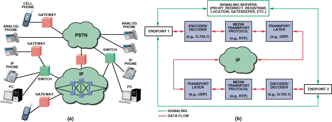
The signaling process involves creating, maintaining, and terminating connections between nodes.
In order to reduce network bandwidth requirements, audio and video are encoded before transmission and decoded during reception. This compression and conversion process is governed by various codec standards for both audio and video streams.
The compressed packets move through the network governed by one or more transport protocols. A switching gateway ensures that the packet set is interoperable at the destination with another IP-based system or a PSTN system. At its final destination, the packet set is decoded and converted back to an audio/video signal, at which point it is played through the receiver’s speakers and/or display unit.
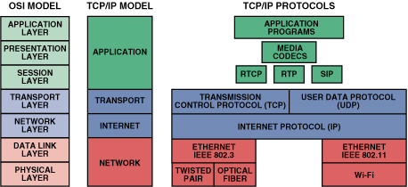
The OSI (Open Systems Interconnection) seven-layer model (Figure 2) specifies a framework for networking. If there are two parties to a communication session, data generated by each starts at the top, undergoing any required configuration and processing through the layers, and is finally delivered to the physical layer for transmission across the medium. At the destination, processing occurs in the reverse direction, until the packets are finally reassembled and the data is provided to the second user.
Session Control: H.323 vs. SIP
The first requirement in a VoIP system is a session-control protocol to establish presence and locate users, as well as to set up, modify, and terminate sessions. There are two protocols in wide use today. Historically, the first of these protocols was H.323*, but SIP (Session Initiation Protocol) is rapidly becoming the main standard. Let’s take a look at the role played by each.
International Telecommunication Union (ITU) H.323
H.323 is an ITU standard originally developed for real-time multimedia (voice and video) conferencing and supplementary data transfer. It has rapidly evolved to meet the requirements of VoIP networks. It is technically a container for a number of required and optional network and media codec standards. The connection signaling part of H.323 is handled by the H.225 protocol, while feature negotiation is supported by H.245.
SIP (Session Initiation Protocol)
SIP is defined by the IETF (Internet Engineering Task Force) under RFC 3261. It was developed specifically for IP telephony and other Internet services—and though it overlaps H.323 in many ways, it is usually considered a more streamlined solution.
SIP is used with SDP (Session Description Protocol) for user discovery; it provides feature negotiation and call management. SDP is essentially a format for describing initialization parameters for streaming media during session announcement and invitation. The SIP/SDP pair is somewhat analogous to the H.225/H.245 protocol set in the H.323 standard.
SIP can be used in a system with only two endpoints and no server infrastructure. However, in a public network, special proxy and registrar servers are utilized for establishing connections. In such a setup, each client registers itself with a server, in order to allow callers to find it from anywhere on the Internet.
Transport Layer Protocols
The signaling protocols above are responsible for configuring multimedia sessions across a network. once the connection is set up, media flows between network nodes are established by utilizing one or more data-transport protocols, such as UDP or TCP.
UDP (User Datagram Protocol)
UDP is a network protocol covering only packets that are broadcast out. There is no acknowledgement that a packet has been received at the other end. Since delivery is not guaranteed, voice transmission will not work very well with UDP alone when there are peak loads on a network. That is why a media transport protocol, like RTP, usually runs on top of UDP.
TCP (Transmission Control Protocol)
TCP uses a client/server communication model. The client requests (and is provided) a service by another computer (a server) in the network. Each client request is handled individually, unrelated to any previous one. This ensures that “free” network paths are available for other channels to use.
TCP creates smaller packets that can be transmitted over the Internet and received by a TCP layer at the other end of the call, such that the packets are “reassembled” back into the original message. The IP layer interprets the address field of each packet so that it arrives at the correct destination.
Unlike UDP, TCP does guarantee complete receipt of packets at the receiving end. However, it does this by allowing packet retransmission, which adds latencies that are not helpful for real-time data. For voice, a late packet due to retransmission is as bad as a lost packet. Because of this characteristic, TCP is usually not considered an appropriate transport for real-time streaming media transmission.
Figure 2 shows how the TCP/IP Internet model, and its associated protocols, compares with and utilizes various layers of the OSI model.
Media Transport
As noted above, sending media data directly over a transport protocol is not very efficient for real-time communication. Because of this, a media transport layer is usually responsible for handling this data in an efficient manner.
RTP (Real-Time Transport Protocol)
RTP provides delivery services for real-time packetized audio and video data. It is the standard way to transport real-time data over IP networks. The protocol resides on top of UDP to minimize packet header overhead—but at a cost; there is no guarantee of reliability or packet ordering. Compared to TCP, RTP is less reliable—but it has less latency in packet transmission, since its packet header overhead is much smaller than for TCP (Figure 3).

In order to maintain a given QoS level, RTP utilizes timestamps, sequence numbering, and delivery confirmation for each packet sent. It also supports a number of error-correction schemes for increased robustness, as well as some basic security options for encrypting packets.
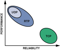
Figure 4 compares performance and reliability of UDP, RTP, and TCP.
RTCP (RTP Control Protocol)
RTCP is a complementary protocol used to communicate control information, such as number of packets sent and lost, jitter, delay, and endpoint descriptions. It is most useful for managing session time bases and for analyzing QoS of an RTP stream. It also can provide a backchannel for limited retransmission of RTP packets.
Media Codecs
At the top of the VoIP stack are protocols to handle the actual media being transported. There are potentially quite a few audio and video codecs that can feed into the media transport layer. A sampling of the most common ones can be found in the sidebar on the last page of this article.
A number of factors help determine how desirable a codec is—including how efficiently it makes use of available system bandwidth, how it handles packet loss, and what costs are associated with it, including intellectual-property royalties.
Blackfin VoIP Collateral
Unlike traditional VoIP embedded solutions that utilize two processor cores to provide VoIP functionality, Blackfin processors provide a convergent solution in a unified core architecture that allows voice and video signal processing concurrent with RISC MCU processing to handle network- and user-interface demands. This unique ability to offer full VoIP functionality on a single convergent processor provides for a unified software development environment, faster system debugging and deployment, and lower overall system cost.
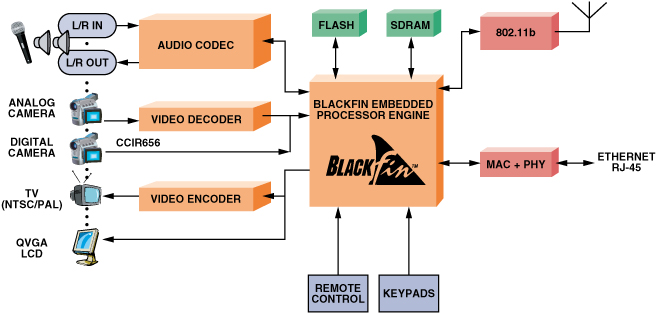
As an example, the ADSP-BF537 Blackfin processor family provides the necessary degree of integration and performance, with low power consumption, for VoIP deployment. It features multiple integrated serial ports (for glueless connection to audio analog-to-digital (A/D) and digital-to-analog (D/A) converters), an external memory controller, a parallel peripheral interface (PPI) for LCD or video encoder/decoder connectivity, and a 10/100baseT Ethernet MAC. If necessary, a second Ethernet MAC can be accommodated via the external memory interface.
A complete communication channel—including voice and networking stack—uses less than 75 MIPS of the processing bandwidth. With ADSP-BF537 performance at up to 600 MHz, there is plenty of available processor “horsepower” to spread across a VoIP product portfolio, as features such as multimedia compression or decompression become necessary. In contrast, competing dedicated VoIP choices are typically performance-limited and offer little or no ability to add features or differentiation.
For VoIP applications, Blackfin-based designs target high-quality, low-channel-count VoIP solutions—with processing headroom to accommodate added features such as music, video, and image transport, as well as overall system control. Here is a sampling of available VoIP offerings, ranging from open-source solutions to high-volume OEM reference designs:
Blackfin/Linphone
A Blackfin VoIP system can be designed using open-source software based on μClinux, the embedded version of the popular GNU/Linux OS. One such General Public License (GPL-licensed) IP-phone package, called Linphone—based on the SIP suite—has been ported to μClinux for Blackfin processors, allowing the Blackfin reference design to communicate with any SIP-compatible endpoint. In a public network with the proper SIP servers and gateway infrastructure, this system can even be used to connect to phones on a PSTN node. For voice encoding and decoding, the current Blackfin implementation of Linphone supports: G.711 (A-law and m-law), GSM (Global System for Mobile Communications), and the Speex audio compression format.
The main components used in the Blackfin Linphone reference design are:
Linux TCP/IP networking stack: includes necessary transport and control protocols, such as TCP and UDP.
Linphone: the main VoIP application, which includes Blackfin-based G.711 and GSM codec implementations. It comprises both a graphical user interface (GUI) for desktop PCs and a simple command-line application for nongraphical embedded systems.
oRTP: an implementation of an RTP stack developed for Linphone and released under the LGPL license.
oSIP: a thread-safe implementation of the SIP protocol released under the LGPL license.
Speex: the open-source reference implementation of the Speex codec. Blackfin-specific optimizations to the fixed-point Speex implementation have been contributed back to the mainline code branch.
Unicoi Systems Blackfin-based Fusion Voice Gateway
The Fusion Voice Gateway (Figure 5) is a complete Voice Gateway/Terminal Adapter Reference Design from Unicoi Systems. With router functionality and full-featured SIP telephony running on a single-core Blackfin Processor, the Fusion Voice Gateway allows for quick time-to-market for terminal adapters.

The Fusion Voice Gateway features robust functionality, including G.168 echo cancellation and multiple G.7xx voice codecs. The Fusion reference design also includes full-featured telephony and router functionality by combining an Internet router, a 4-port Ethernet switch and VoIP gateway functionality.
Unicoi Systems Blackfin-based Fusion IP Phone
The Fusion IP Phone from Unicoi Systems is a complete software/silicon solution that offers a full-featured platform supporting current and emerging IP phone standards, and has expansion capabilities for product differentiation.
The Fusion IP Phone Reference Design reduces BOM cost as well as the time and complexity often associated with developing an IP phone. Designed around the ADSP-BF536, the reference design software delivers the critical processing (e.g., real-time operating system, call manager, voice algorithms, acoustic echo cancellation for full-duplex speakerphone), communication protocols (TCP/IPv4/v6, SIP, RTP, etc.), and peripheral functions (LCD and keypad controllers, etc.) required to build a basic or advanced IP phone.
Blackfin BRAVO VoIP Reference Designs
The Analog Devices Blackfin BRAVOTM VoIP and Videophone reference designs are complete system solutions for OEMs building feature-rich, high-performance, low-cost VoIP desktop phones, videophones, and telephone adapters. The designs include the complete suite of software for VoIP applications, all controlled by a comprehensive set of application program interfaces (APIs) for customization and control of core system functions.
For audio, the designs support multiple G.7xx audio codecs, G.168-compliant network echo cancellation, and acoustic echo cancellation for enhanced audio clarity. Optionally, RF transceivers can be included in the design to provide wireless audio capability. The designs support both H.323- and SIP-compliant software stacks.
On the video front, the BRAVO Broadband Audio/Video Communications reference design (Figure 6) provides up to 30 frames per second of common intermediate format (CIF) color video, including support for ITU-standard H.263 and H.264 video codecs, picture-in-picture, high-resolution graphics with overlay, alpha and chroma keying, and antiflicker filtering.
Conclusion
Clearly, VoIP technology has the potential to revolutionize the way people communicate—whether they’re at home or at work, plugged-in or untethered, video-enabled or just plain audio-minded. The power and versatility of Blackfin Processors, working with a wide variety of standards, will make VoIP increasingly pervasive in embedded environments, creating value-added features in many markets that are not yet experiencing the benefits of this exciting technology.
*To be exact, the task of session control and initiation lies in the domain of H.225.0 and H.245, which are part of the H.323 umbrella protocal.
Media Codec Standards
Audio Codecs
G.711
Introduced in 1988, G.711—the international standard for encoding telephone audio on a 64-kbps channel—is the simplest standard among the options presented here. The only compression used in G.711 is companding (using either the m-law or A-law standards), which compresses each data sample to an 8-bit word, yielding an output bit rate of 64 kbps. The H.323 standard specifies that G.711 must be present as a baseline for voice communication.
G.723.1
G.723.1 is an algebraic code-excited linear-prediction (ACELP)-based dual-bit-rate codec, released in 1996 to target VoIP applications. The encoding time frame for G.723.1 is 30 ms. Each frame can be encoded in 20 bytes or 24 bytes, thus translating to 5.3-kbps or 6.3-kbps streams, respectively. The bit rates can be effectively reduced through voice-activity detection and comfort-noise generation. The codec offers good immunity against network imperfections—like lost frames and bit errors. G.723.1 is suitable for video-conferencing applications, as described by the H.324 family of international standards for multimedia communication.
G.729
Another speech codec, released in 1996, is the low-latency G.729 audio data-compression algorithm, which partitions speech into 10-ms frames. It uses an algorithm called conjugate-structure ACELP (CS-ACELP). G.729 compresses 16-bit signals sampled at 8 kHz via 10-ms frames into a standard bit rate of 8 kbps, but it also supports 6.4-kbps and 11.8-kbps rates. In addition, it supports voice-activity detection and comfort-noise generation.
GSM
The GSM speech codecs find use in cell-phone systems around the world. The governing body for these standards is the European Telecommunications Standards Institute (ETSI). Standards in this domain have evolved since the first one, GSM Full Rate (GSM-FR). This standard uses a CELP variant called regular pulse-excited linear predictive coder (RPELPC). The input speech signal is divided into 20-ms frames. Each frame is encoded as 260 bits, thereby producing a total bit rate of 13 kbps. Free GSM-FR implementations are available for use under certain restrictions.
Speex
Speex, an Open Source/Free Software audio compression format designed for speech codecs, was released by Xiph.org, with the goal of being a totally patent-free speech solution. Like many other speech codecs, Speex is based on CELP with residue coding. It can code 8-kHz, 16-kHz, and 32-kHz linear PCM signals into bit rates ranging from 2 kbps to 44 kbps. Speex is resilient to network errors, and it supports voice-activity detection. Besides allowing variable bit rates, Speex also has the unique feature of stereo encoding. Source code is available from Speex.org that includes assembly-level optimization for narrow-band compression, as well as a Blackfin-based echo canceller.
Video Codecs
H.261
This standard, developed in 1990, was the first widely used video codec. It introduced the idea of segmenting a frame into 16 × 16 “macroblocks” that are tracked between frames to establish motion-compensation vectors. It is mainly targeted at videoconferencing applications over ISDN lines (p × 64 kbps, where p ranges from 1 to 30). Input frames are typically CIF (352 × 288) at 30 frames-per-second (fps), and output compressed frames occupy 64 kbps to 128 kbps for 10-fps resolution. Although still used today, it has been largely superseded by H.263. Nevertheless, H.323 specifies that H.261 must be present as a baseline for video communication.
H.263
This codec is ubiquitous in videoconferencing, outperforming H.261 at all bit rates. Input sources are usually quarter-common intermediate format (QCIF) (176 × 144) or CIF at 30 fps, and output bit rates can be less than 28.8 kbps at 10 fps, for the same performance as H.261. So whereas H.261 needed an ISDN (integrated-services-digital-network) line, H.263 can use ordinary phone lines. H.263 finds use in end markets such as video telephony and networked surveillance, and it is popular in IP-based applications.