3 体系的详细设计方案
3.1 概述
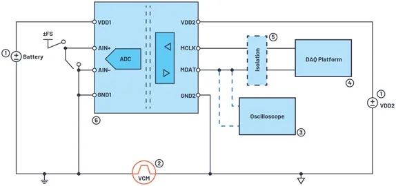
在组播网络的拓扑图中,编码路由器、转发路由器和解码路由器是三个独立的体系,各自完结编码、转发和解码的使命。前面讲过,分组的编码、解码首要在网络层完结。在网络层中数据通道中,data bus和ctrl bus是同步传输的,二者之间的联系和格局如图3.1-1所示:
|
ctrl bus(8位) |
Data bus(64位) |
|
ff |
module header |
|
00 |
Pkt data1 |
|
00 |
…… |
|
xy(xy≠00) |
Last pkt data |
图3.1-1 数据通道中的data bus和ctrl bus
Ctrl为ff时,表明为一个数据包的包头,xy为非零数据,指明最终一个有用的字节地点的方位,如01000000指明是第7个,即data[63:48]为有用数据。模块之间数据传输的进程是:若上一个模块现已处理结束,想把数据传输到下一个模块,首要判别输入信号rdy是否有用,当rdy = 1时,将数据和操控信号同步发送出去,一起wr_vld信号有用,时序如图3.1-2所示:
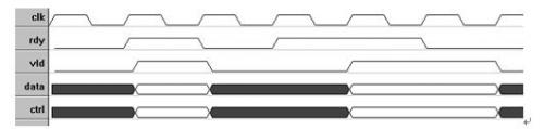
图3.1-2 有用的数据传输时序
3.2 编码路由器详细设计方案
3.2.1编码体系全体模块如图3.2-1所示
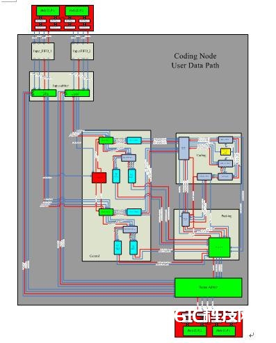
图3.2-1:编码体系全体模块图
3.2.2体系中各单元模块的功用与时序
(1)Input arbiter
① Input arbiter内部结构如图3.2-2所示:
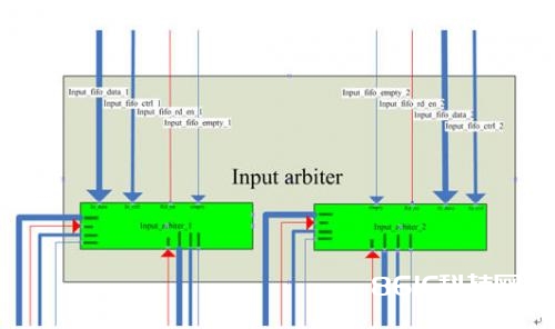
图3.2-2 Input arbiter内部结构图
② 本模块输入输出信号列表及阐明
|
Signal name |
Bit width |
Input or output |
description |
|
Input_fifo_data_1 |
64 |
input |
Input data bus from “input FIFO 1” |
|
Input_fifo_ctrl_1 |
8 |
input |
Input ctrl bus from “input FIFO 1” |
|
Input_fifo_empty_1 |
1 |
input |
1=input FIFO is empty,0=otherwise |
|
Input_fifo_rd_en_1 |
1 |
output |
Read enable |
|
Input_fifo_data_2 |
64 |
input |
Input data bus from “input FIFO 2” |
|
Input_fifo_ctrl_2 |
8 |
input |
Input ctrl bus from “input FIFO 2” |
|
Input_fifo_empty_2 |
1 |
input |
1=input FIFO is empty,0=otherwise |
|
Input_fifo_rd_en_2 |
1 |
output |
Read enable |
|
Data_arbiter_ctrl_1 |
64 |
output |
Output data bus to “control module” |
|
Ctrl_arbiter_ctrl_1 |
8 |
Output |
Output ctrl bus to “control module” |
|
Val_arbitrer_ctrl_1 |
1 |
Output |
1=data from input arbiter 1 to head splitter 1 is valid, 0=otherwise |
|
Rdy_arbiter_ctrl_1 |
1 |
Input |
1=module “head splitter 1” is ready to receive |
|
Data_arbiter_ctrl_2 |
64 |
output |
Output data bus to “control module” |
|
Ctrl_arbiter_ctrl_2 |
8 |
Output |
Output ctrl bus to “control module” |
|
Val_arbitrer_ctrl_2 |
1 |
Output |
1=data from input arbiter 2 to head splitter 2 is valid, 0=otherwise |
|
Rdy_arbiter_ctrl_2 |
1 |
Input |
1=module “head splitter 2” is ready to receive, 0=otherwise |
|
Data_arbiter_out_1 |
64 |
output |
Output data bus to “output arbiter module” |
|
Ctrl_arbiter_out_1 |
8 |
Output |
Output ctrl bus to “output arbiter module” |
|
Val_arbiter_out_1 |
1 |
Output |
1=data from input arbiter 1 to output arbiter is valid, 0=otherwise |
|
Rdy_arbiter_out_1 |
1 |
Input |
1=module “output arbiter” is ready to receive from input arbiter 1, 0=otherwise |
|
Data_arbiter_out_2 |
64 |
output |
Output data bus to “output arbiter module” |
|
Ctrl_arbiter_out_2 |
8 |
Output |
Output ctrl bus to “output arbiter module” |
|
Val_arbiter_out_2 |
1 |
Output |
1=data from input arbiter 2 to output arbiter is valid, 0=otherwise |
|
Rdy_arbiter_out_2 |
1 |
Input |
1=module “output arbiter” is ready to receive from input arbiter 2, 0=otherwise |
|
clk |
1 |
Input |
System clock, running at 125MHz |
|
Rst_n |
1 |
input |
System asynchronous reset signal |
③ 功用描述及数据流
本模块履行输入裁定功用。两个独立的input arbiter模块别离从两个输入FIFO读出数据包,判别数据包类型,决议输出端口(非IP包直接送往output arbiter,IP包送往control),输出数据。
为了判别数据包类型,需求获取16-bit Ether Type信息,该信息坐落每个数据包第二个double word中的31:16位,若Ether Type为0x0080,则阐明此数据包为IP数据包,若Ether Type值不是0x0080,则阐明此数据包不是IP数据包,将被直接送往output arbiter模块。
④ 要害时序及状况机
本模块的状况机的状况转化如图3.2-3所示

图3.2-3:input arbiter状况转化图
2、Control
① 子模块列表
|
Sub module name |
quantity |
description |
|
Head_spliter |
2 |
Split head and payload, send head to “head info extractor”, send payload to “FIFO ctrl payload” |
|
Head_info_extractor |
2 |
Receive head from “head splitter”, extract “source number”, generate “generation number”. Store legacy head and packing info head respectively in “FIFO ctrl legacy” and “FIFO ctrl packinginfo” |
|
Control_arbiter |
1 |
Detect ctrl bus to determine whether should process both channels synchronously or hold one channel and process the other. |
|
FIFO ctrl payload |
2 |
Standard FIFO generated by CoreGen, store payload |
|
FIFO ctrl legacy |
2 |
Standard FIFO generated by CoreGen, store legacy head |
|
FIFO ctrl packinginfo |
2 |
Standard FIFO generated by CoreGen, store packing info head |
② 内部结构如图3.2-4
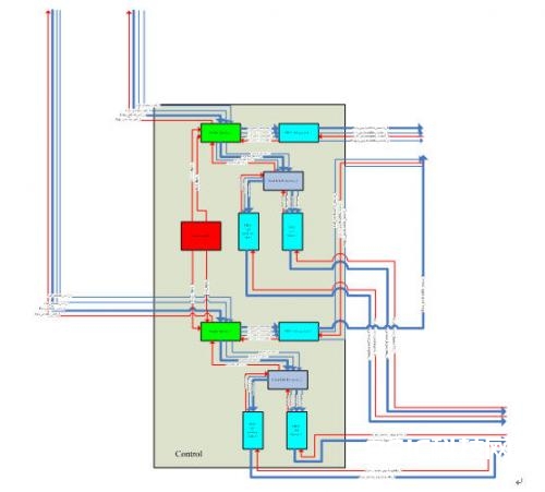
图3.2-4:control模块内部结构
③ 本模块输入输出信号列表及阐明
|
Signal name |
Bit width |
Input or output |
description |
|
Data_arbiter_ctrl_1 |
64 |
Input |
Input data bus from “input arbiter 1” |
|
Ctrl_arbiter_ctrl_1 |
8 |
Input |
Input ctrl bus from “input arbiter 1” |
|
Val_arbiter_ctrl_1 |
1 |
Input |
1=data from input arbiter 1 to head splitter 1 is valid, 0=otherwise |
|
Rdy_arbiter_ctrl_1 |
1 |
output |
1=module “head splitter 1” is ready to receive from input arbiter 1, 0=otherwise |
|
Data_arbiter_ctrl_2 |
64 |
Input |
Input data bus from “input arbiter 2” |
|
Ctrl_arbiter_ctrl_2 |
8 |
Input |
Input ctrl bus from “input arbiter 2” |
|
Val_arbiter_ctrl_2 |
1 |
Input |
1=data from input arbiter 2 to head splitter 2 is valid, 0=otherwise |
|
Rdy_arbiter_ctrl_2 |
1 |
output |
1=module “head splitter 2” is ready to receive from input arbiter 2, 0=otherwise |
|
Data_payloadfifo_router_1 |
64 |
output |
output data bus to “payload router” |
|
Ctrl_payloadfifo_router_1 |
8 |
output |
Output ctrl bus to “payload router” |
|
Rd_en_payloadfifo_router_1 |
1 |
Input |
Read enable |
|
Empty_payloadfifo_router_1 |
1 |
output |
1=FIFO ctil payload 1 is empty,0=otherwise |
|
Data_payloadfifo_router_2 |
64 |
output |
output data bus to “payload router” |
|
Ctrl_payloadfifo_router_2 |
8 |
output |
Output ctrl bus to “payload router” |
|
Rd_en_payloadfifo_router_2 |
1 |
Input |
Read enable |
|
Empty_payloadfifo_router_2 |
1 |
output |
1=FIFO ctrl payload 2 is empty,0=otherwise |
|
Data_center_legacyfifo_1 |
64 |
Output |
Output data bus to “packing center” |
|
Rd_en_center_legacyfifo_1 |
1 |
Input |
Read enable |
|
Data_center_packingfifo_1 |
14 |
Output |
Output data bus to “packing center” |
|
Rd_en_center_packingfifo_1 |
1 |
input |
Read enable |
|
Data_center_legacyfifo_2 |
64 |
Output |
Output data bus to “packing center” |
|
Rd_en_center_legacyfifo_2 |
1 |
Input |
Read enable |
|
Data_center_packingfifo_2 |
14 |
Output |
Output data bus to “packing center” |
|
Rd_en_center_packingfifo_2 |
1 |
input |
Read enable |
|
clk |
1 |
input |
System clock, running at 125MHz |
|
Rst_n |
1 |
input |
System asynchronous reset signal |
④ 功用描述及数据流
本模块为主操控模块。子模块control arbiter经过监控两条输入通道的ctrl bus,操控子模块head_spliter的两个独立的例化。详细操控操作如下:
若两条输入通道一起进来新的IP包,则一起处理两条通道。
若输入通道1进来新IP包时,通道2中IP包现已在处理中,则堵塞通道1,直至通道2处理结束再从头判定。
若一起处理两条通道时,两条通道中的数据包深度相同,则无需“PADDING”操作。若通道1中数据包发送结束时(ctrl bus用one-hot-code标明结束字节),通道2中数据包没有发送结束,则需对通道1中数据包补零,并在ctrl bus顶用0b11110000标明此为padding数据。
子模块head_spliter别离包头和负载,并别离发往head_info_extractor提取封装信息和FIFO_ctrl_payload暂存负载。
子模块head_info_extractor提取包头中的源IP地址,并由此生成4-bit信源编号(source number)和10-bit代编号(generation number),将生成的封装信息存入FIFO_ctrl_packinginfo,将原始包头存入FIFO_ctrl_legacy。
⑤ 要害时序及状况机
Head_spliter状况机如图3.2-5
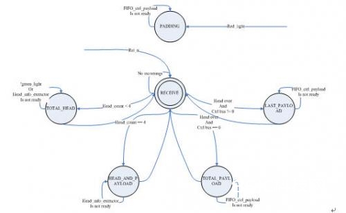
图3.2-5:Head_spliter状况机
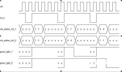
Control arbiter时序图
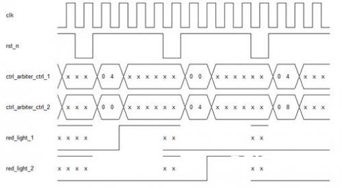
Head spliter时序图
3、Coding
① 子模块列表
|
Submodule name |
quantity |
description |
|
Payload router |
1 |
Determine by the arrival of packets from both channels, whether should process coding or transport directly to packing module |
|
M64×8 multiplier |
2 |
Multiply 64-bit data from “payload router” by 8-bit random number from “prng tap16” |
|
Prng tap16 |
1 |
8-bit random number generator |
|
M72×72 adder |
1 |
72-bit by 72-bit full adder |
|
M72to64 converter |
1 |
Convert data bus width from 72-bit to 64-bit |
② Coding模块的内部结构如图3.2-6
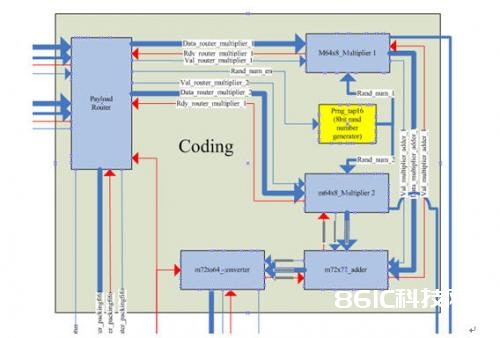
图3.2-6:coding模块内部结构
③ 本模块输入输出信号列表及阐明
|
Signal name |
Bit width |
I/O |
description |
|
Data_payloadfifo_router_1 |
64 |
Input |
Input data bus from “FIFO ctrl payload 1” |
|
Ctrl_payloadfifo_router_1 |
8 |
Input |
Input ctrl bus from “FIFO ctrl payload 1” |
|
empty_payloadfifo_router_1 |
1 |
Input |
1=FIFO ctrl payload 1 is empty,0=otherwise |
|
Rd_en_payloadfifo_rouer_1 |
1 |
output |
Read enable |
|
Data_payloadfifo_router_2 |
64 |
Input |
Input data bus from “FIFO ctrl payload 2” |
|
Ctrl_payloadfifo_router_2 |
8 |
Input |
Input ctrl bus from “FIFO ctrl payload 2” |
|
empty_payloadfifo_router_2 |
1 |
Input |
1=FIFO ctrl payload 2 is empty,0=otherwise |
|
Rd_en_payloadfifo_rouer_2 |
1 |
output |
Read enable |
|
Router status |
3 |
output |
Output FSM state signal to “packing FIFO” and “packing center”, coordinate with the control of packing procedure |
|
Data_router_packingfifo |
73 |
output |
Output data bus to “packing FIFO”. Bit 64 is set to “0” to indicate this is an uncoded packet |
|
Wr_en_router_packingfifo |
1 |
output |
Write enable |
|
Rdy_router_packingfifo |
1 |
input |
1=module “packing FIFO” is ready to receive from payload router, 0=otherwise |
|
Empty_packingfifo |
1 |
input |
1=FIFO packing is empty,0=otherwise |
|
Data_converter_packingfifo |
73 |
output |
Output data bus to “packing FIFO”. Bit 64 is set to “1” to indicate this is a coded packet |
|
Wr_en_converter_packingfifo |
1 |
Output |
Write enable |
|
Rdy_converter_packingfifo |
1 |
output |
1=module “packing FIFO” is ready to receive from m72to64 converter, 0=otherwise |
|
Empty_converterfifo |
1 |
output |
1=FIFO converter is empty,0=otherwise |
|
Rand_num_1 |
8 |
output |
Output random number 1 to “packing center” |
|
Rand_num_2 |
8 |
output |
Output random number 2 to “packing center” |
|
clk |
1 |
input |
System clock running at 125MHz |
|
Rst_n |
1 |
input |
System asynchronous reset signal |
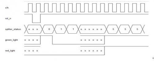
④ 功用描述及数据流
本模块为主运算模块。子模块paylaod router构建与上游模块control的接口,从control的子模块FIFO ctrl payload中读取数据。若两FIFO都非空,则阐明control模块一起处理了两条通道,也即需求进行编码操作。Paylpad router一起读取两个FIFO中的数据,送往由m64×8 multiplier、m72×72 adder以及m72to64 converter组成的“编码流水线”进行编码运算,并向下流packing模块发送编码过的数据包。
子模块prng tap16是8位伪随机数发生器。使能信号rand_num_en有用时,发生一个8位伪随机数。子模块m64×8 multiplier是64乘8位乘法器,该模块将负载与随即系数相乘,得到72位成果。m72×72 adder是72位全加器,将两个乘法器得到的成果相加得到编码输出。m72to64 converter是位宽转化器,因为coding模块输出的数据总线仍需坚持64位,所以需求该转化器将72位编码输出转化为64为编码数据。因为是同步电路,选用同一时钟,该位宽转化将发生必定的数据囤积,需求较大缓存。
⑤ 要害时序与状况机
- Payload router状况机
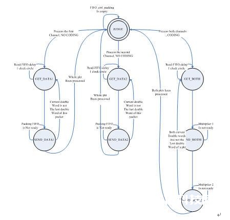
图3.2-7 Payload router状况机