DDR内存条引脚界说图 管脚界说图
DDR2 SDRAM DIMM 240 pin
DDR: Double Data Rate
DIMM: Dual Inline Memory Module
SDRAM: Synchronous Dynamic Random Access Memory, Synchronous to PosiTIve Clock Edge.
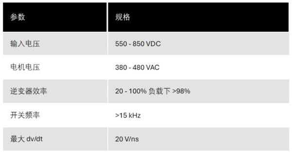
PIN CONFIGURATIONS (Front side / back side)
DIMM: Dual Inline Memory Module
SDRAM: Synchronous Dynamic Random Access Memory, Synchronous to PosiTIve Clock Edge.
PIN CONFIGURATIONS (Front side / back side)
| Front | Back | ||||||||||||||
|---|---|---|---|---|---|---|---|---|---|---|---|---|---|---|---|
| Pin | Symbol | Pin | Symbol | Pin | Symbol | Pin | Symbol | Pin | Symbol | Pin | Symbol | Pin | Symbol | Pin | Symbol |
| 1 | VREF | 31 | DQ19 | 61 | A4 | 91 | VSS | 121 | VSS | 151 | VSS | 181 | VDDQ | 211 | DM5/DQS14 |
| 2 | VSS | 32 | VSS | 62 | VDDQ | 92 | DQS5# | 122 | DQ4 | 152 | DQ28 | 182 | A3 | 212 | NC/DQS14# |
| 3 | DQ0 | 33 | DQ24 | 63 | A2 | 93 | DQS5 | 123 | DQ5 | 153 | DQ29 | 183 | A1 | 213 | VSS |
| 4 | DQ1 | 34 | DQ25 | 64 | VDD | 94 | VSS | 124 | VSS | 154 | VSS | 184 | VDD | 214 | DQ46 |
| 5 | VSS | 35 | VSS | 65 | VSS | 95 | DQ42 | 125 | DM0/DQS9 | 155 | DM3/DQS12 | 185 | CK0 | 215 | DQ47 |
| 6 | DQS0# | 36 | DQS3# | 66 | VSS | 96 | DQ43 | 126 | NC/DQS9# | 156 | NC/DQS12# | 186 | CK0# | 216 | VSS |
| 7 | DQS0 | 37 | DQS3 | 67 | VDD | 97 | VSS | 127 | VSS | 157 | VSS | 187 | VDD | 217 | DQ52 |
| 8 | VSS | 38 | VSS | 68 | PAR_IN | 98 | DQ48 | 128 | DQ6 | 158 | DQ30 | 188 | A0 | 218 | DQ53 |
| 9 | DQ2 | 39 | DQ26 | 69 | VDD | 99 | DQ49 | 129 | DQ7 | 159 | DQ31 | 189 | VDD | 219 | VSS |
| 10 | DQ3 | 40 | DQ27 | 70 | A10/AP | 100 | VSS | 130 | VSS | 160 | VSS | 190 | BA1 | 220 | RFU |
| 11 | VSS | 41 | VSS | 71 | BA0 | 101 | SA2 | 131 | DQ12 | 161 | CB4 | 191 | VDDQ | 221 | RFU |
| 12 | DQ8 | 42 | CB0 | 72 | VDDQ | 102 | NC | 132 | DQ13 | 162 | CB5 | 192 | RAS# | 222 | VSS |
| 13 | DQ9 | 43 | CB1 | 73 | WE# | 103 | VSS | 133 | VSS | 163 | VSS | 193 | S0# | 223 | DM6/DQS15 |
| 14 | VSS | 44 | VSS | 74 | CAS# | 104 | DQS6# | 134 | DM1/DQS10 | 164 | DM8/DQS17 | 194 | VDDQ | 224 | NC/DQS15# |
| 15 | DQS1# | 45 | DQS8# | 75 | VDDQ | 105 | DQS6 | 135 | NC/DQS10# | 165 | NC/DQS17# | 195 | ODT0 | 225 | VSS |
| 16 | DQS1 | 46 | DQS8 | 76 | S1# | 106 | VSS | 136 | VSS | 166 | VSS | 196 | NC/A13 | 226 | DQ54 |
| 17 | VSS | 47 | VSS | 77 | 0DT1 | 107 | DQ50 | 137 | RFU | 167 | CB6 | 197 | VDD | 227 | DQ55 |
| 18 | RESET# | 48 | CB2 | 78 | VDDQ | 108 | DQ51 | 138 | RFU | 168 | CB7 | 198 | VSS | 228 | VSS |
| 19 | NC | 49 | CB3 | 79 | VSS | 109 | VSS | 139 | VSS | 169 | VSS | 199 | DQ36 | 229 | DQ60 |
| 20 | VSS | 50 | VSS | 80 | DQ32 | 110 | DQ56 | 140 | DQ14 | 170 | VDDQ | 200 | DQ37 | 230 | DQ61 |
| 21 | DQ10 | 51 | VDDQ | 81 | DQ33 | 111 | DQ57 | 141 | DQ15 | 171 | CKE1 | 201 | VSS | 231 | VSS |
| 22 | DQ11 | 52 | CKE0 | 82 | VSS | 112 | VSS | 142 | VSS | 172 | VDD | 202 | DM4/DQS13 | 232 | DM7/DQS16 |
| 23 | VSS | 53 | VDD | 83 | DQS4# | 113 | DQS7# | 143 | DQ20 | 173 | NC | 203 | NC/DQS13# | 233 | NC/DQS16# |
| 24 | DQ16 | 54 | NC/BA2 | 84 | DQS4 | 114 | DQS7 | 144 | DQ21 | 174 | NC | 204 | VSS | 234 | VSS |
| 25 | DQ17 | 55 | ERR_OUT | 85 | VSS | 115 | VSS | 145 | VSS | 175 | VDDQ | 205 | DQ38 | 235 | DQ62 |
| 26 | VSS | 56 | VDDQ | 86 | DQ34 | 116 | DQ58 | 146 | DM2/DQS11 | 176 | A12 | 206 | DQ39 | 236 | DQ63 |
| 27 | DQS2# | 57 | A11 | 87 | DQ35 | 117 | DQ59 | 147 | NC/DQS11# | 177 | A9 | 207 | VSS | 237 | VSS |
| 28 | DQS2 | 58 | A7 | 88 | VSS | 118 | VSS | 148 | VSS | 178 | VDD | 208 | DQ44 | 238 | VDDSPD |
| 29 | VSS | 59 | VDD | 89 | DQ40 | 119 | SDA | 149 | DQ22 | 179 | A8 | 209 | DQ45 | 239 | SA0 |
| 30 | DQ18 | 60 | A5 | 90 | DQ41 | 120 | SCL | 150 | DQ23 | 180 | A6 | 210 | VSS | 240 | SA1 |
Note: Pin 196 is NC for 512MB, or A13 for 1GB and 2GB; pin 54 is NC for 512MB and 1GB, or BA2 for 2GB.
Pin DescripTIons
Pin numbers may not correlate with symbols; refer to Pin Assignment table above for more informaTIon.
| Pin Numbers | Symbol | Type | Description |
|---|---|---|---|
| 195 | ODT0 | Input | On-Die Termination: ODT (registered HIGH) enables termination resistance internal to the DDR2 SDRAM. When enabled, ODT is only applied to each of the following pins: DQ, DQS, DQS#, RDQS, RDQS#, CB, and DM. The ODT input will be ignored if disabled via the LOAD MODE command. |
| 185, 186 | CK0, CK0# | Input | Clock: CK and CK# are differential clock inputs. All address and control input signals are sampled on the crossing of the positive edge of CK and negative edge of CK#. Output data (DQs and DQS/DQS#) is referenced to the crossings of CK and CK#. |
| 52 | CKE0 | Input | Clock Enable: CKE (registered HIGH) activates and CKE (registered LOW) deactivates clocking circuitry on the DDR2 SDRAM. The specific circuitry that is enabled/disabled is dependent on the DDR2 SDRAM configuration and operating mode. CKE LOW provides PRECHARGE POWER-DOWN and SELF REFRESH operations (all device banks idle), or ACTIVE POWERDOWN (row ACTIVE in any device bank). CKE is synchronous for POWER-DOWN entry, POWER-DOWN exit, output disable, and for SELF REFRESH entry. CKE is asynchronous for SELF REFRESH exit. Input buffers (excluding CK, CK#, CKE, and ODT) are disabled during POWER-DOWN. Input buffers (excluding CKE) are disabled during SELF REFRESH. CKE is an SSTL_18 input but will detect a LVCMOS LOW level once VDD is applied during first power-up. After Vref has become stable during the power on and initialization sequence, it must be maintained for proper operation of the CKE receiver. For proper self-refresh operation VREF must be maintained to this input. |
| 193 | S0# | Input | Chip Select: S# enables (registered LOW) and disables (registered HIGH) the command decoder. All commands are masked when S# is registered HIGH. S# provides for external rank selection on systems with multiple ranks. S# is considered part of the command code. |
| 73, 74, 192 | RAS#, CAS#, WE# | Input | Command Inputs: RAS#, CAS#, and WE# (along with S#) define the command being entered. |
| 54 (2GB), 71, 190 | BA0, BA1, BA2 (2GB) | Input | Bank Address Inputs: BA0–BA1/BA2 define to which device bank an ACTIVE, READ, WRITE, or PRECHARGE command is being applied. BA0–BA1 define which mode register including MR, EMR, EMR(2), and EMR(3) is loaded during the LOAD MODE command. |
| 57, 58, 60, 61, 63, 70, 176, 177, 179, 180, 182, 183, 188, 196 (1GB, 2GB) | A0–A12 (512MB) A0–A13 (1GB, 2GB) | Input | Address Inputs: Provide the row address for ACTIVE commands, and the column address and auto precharge bit (A10) for Read/ Write commands, to select one location out of the memory array in the respective bank. A10 sampled during a PRECHARGE command determines whether the PRECHARGE applies to one device bank (A10 LOW, device bank selected by BA0–BA1/BA2) or all device banks (A10 HIGH). The address inputs also provide the op-code during a LOAD MODE command. |
| 3, 4, 9, 10, 12, 13, 21, 22, 24, 25, 30, 31, 33, 34, 39, 40, 80, 81, 86, 87, 89, 90, 95, 96, 98, 99, 107, 108, 110, 111, 116, 117, 122, 123, 128, 129, 131, 132, 140, 141, 143, 144, 149, 150, 152, 153, 158, 159, 199, 200, 205, 206, 208, 209, 214, 215, 217, 218, 226, 227, 229, 230, 235, 236 | DQ0–DQ63 | I/O | Data Input/Output: Bidirectional data bus. |
| 6, 7, 15, 16, 27, 28, 36, 37, 45, 46, 83, 84, 92, 93, 104, 105, 113, 114, 126, 135, 147, 156, 165, 203, 212, 224, 233 125, 134, 146, 155, 164, 202, 211, 223, 232 | DQS0–DQS8, DQS0#– DQS17#, DM0–DM8 (DQS9– DQS17) | I/O | Data Strobe: Output with read data, input with write data for source synchronous operation. Edge-aligned with read data, center aligned with write data. DQS# is only used when differential data strobe mode is enabled via the LOAD MODE command. Input Data Mask: DM is an input mask signal for write data. Input data is masked when DM is sampled HIGH along with that input data during a WRITE access. DM is sampled on both edges of DQS. Although DM pins are input-only, the DM loading is designed to match that of DQ and DQS pins. If RDQS is disabled, DQS0–DQS17 become DM0–DM8 and DQS9#–DQS17# are not used. |
| 42, 43, 48, 49, 161, 162, 167, 168 | CB0–CB7 | I/O | Check Bits. |
| 68 | PAR_IN | Input | Parity bit for the address and control bus. |
| 55 | ERR_OUT | Output | Parity error found on the address and control bus. |
| 120 | SCL | Input | Serial Clock for Presence-Detect: SCL is used to synchronize the presence-detect data transfer to and from the module. |
| 101, 239, 240 | SA0–SA2 | Input | Presence-Detect Address Inputs: These pins are used to configure the presence-detect device. |
| 119 | SDA | I/O | Serial Presence-Detect Data: SDA is a bidirectional pin used to transfer addresses and data into and out of the presence-detect portion of the module. |
| 18 | RESET# | Input | Asynchronously forces all registered outputs LOW when RESET# is LOW. This signal can be used during power up to ensure that CKE is LOW and DQs are High-Z. |
| 53, 59, 64, 67, 69, 172, 178, 184, 187, 189, 197, | VDD | Supply | Power Supply: 1.8V ±0.1V. |
| 51, 56, 62, 72, 75, 78, 170, 175, 181, 191, 194, | VDDQ | Supply | DQ Power Supply: 1.8V ±0.1V. |
| 1 | VREF | Supply | SSTL_18 reference voltage. |
| 2, 5, 8, 11, 14, 17, 20, 23, 26, 29, 32, 35, 38, 41, 44, 47, 50, 65, 66, 79, 82, 85, 88, 91, 94, 97,100, 103, 106, 109,112, 115, 118, 121, 124, 127, 130, 133, 136, 139, 142, 145, 148, 151, 154, 157, 160, 163, 166, 169, 198, 201, 204, 207, 210, 213, 216, 219, 222, 225, 228, 231, 234, 237 | VSS | Supply | Ground. |
| 238 | VDDSPD | Supply | Serial EEPROM positive power supply: +1.7V to +3.6V. |
| 19, 54 (512MB, 1GB), 76, 77, 102, 171, 196 (512MB), 173, 174, | NC | — | No Connect: These pins should be left unconnected. |
| 137, 138, 220, 221 | RFU | — | Reserved for future use. |